


Dear e2e support,
My customer is facing some difficulties with the regulation of our buck-boost (details below).
The specifications are:
- Vin from 9VDC to 36VDC.
- Vout = 24V
- Iout = 5A. Estimated peak power = 120W
The 24Vout is intended to power a thermal printer
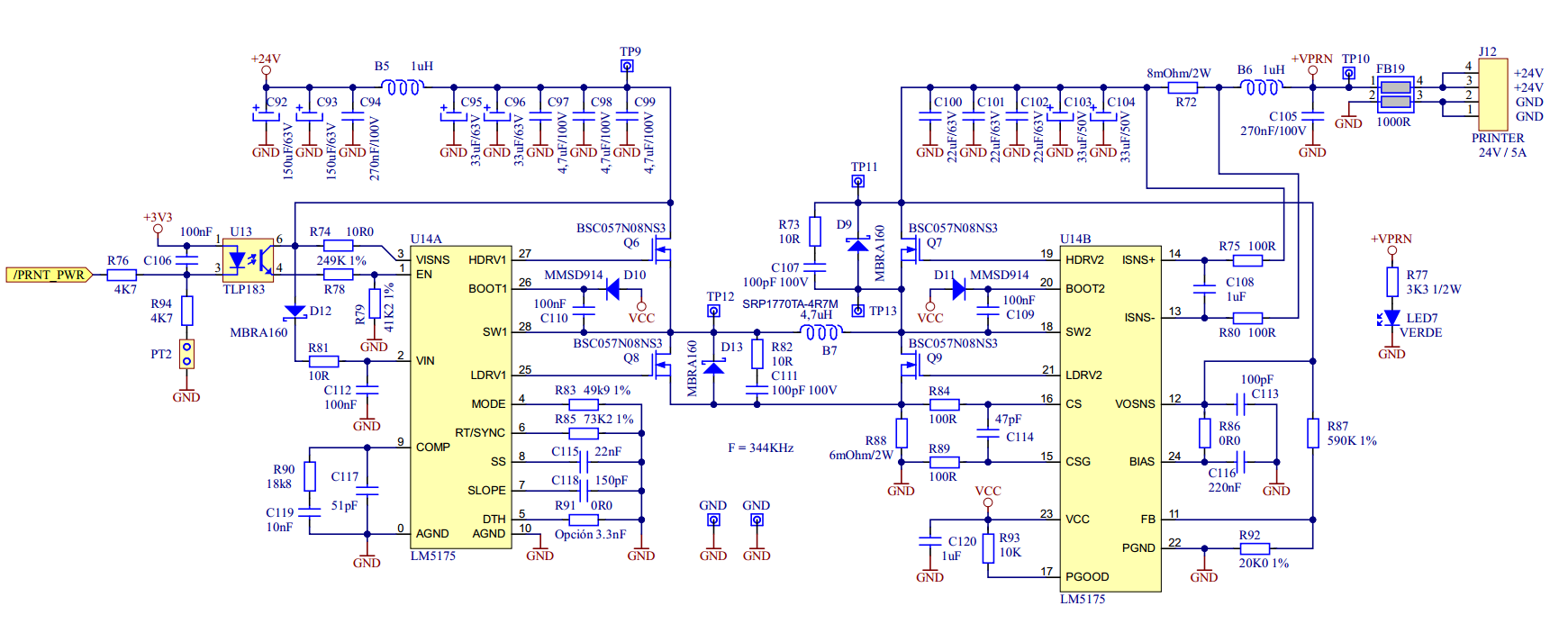
Their schematic:
Test results:
Using a RESISTIVE LOAD
- Vin = 9V. It Works fine.
- Vin = 36V. It Works fine.
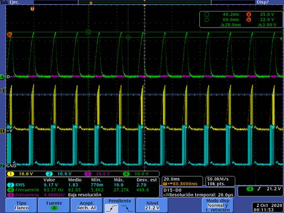
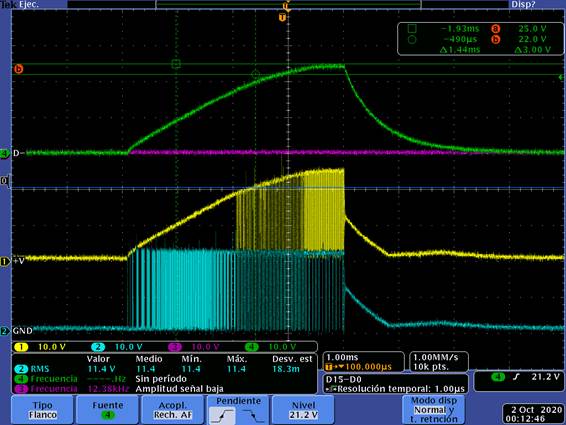
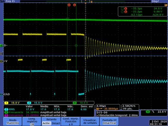
- Vin = From 22 to 20V (more or less) it doesn’t work fine, the output voltage falls down. The DC/DC controller seems not to recognize the right working mode (BOOST/BUCK), see the following diagrams:
Channel 1: TP13
Channel 2: TP12
Channel 4: Output voltage
- Vin = 20~22V. Reducing the load to 10Ω, it already works fine.
- Vin = 20~22V. with 5Ω again and mounting a new SLOPE capacitor (300pF), it works fine.
- With a 450pF SOPE capacitor it works a little worse.
Using the thermal printer as a load:
- Vin = 9V. It Works fine.
- Vin = 36V. It Works fine.
- Vin = From 22 to 20V (more or less) it doesn’t work fine, the printing results are not very good. The output voltage drops down while the printer is printing for the demanded current.
- With a 450pF SOPE capacitor it works worse.
Could you share your recommendations / schematic review?
Regards,

