


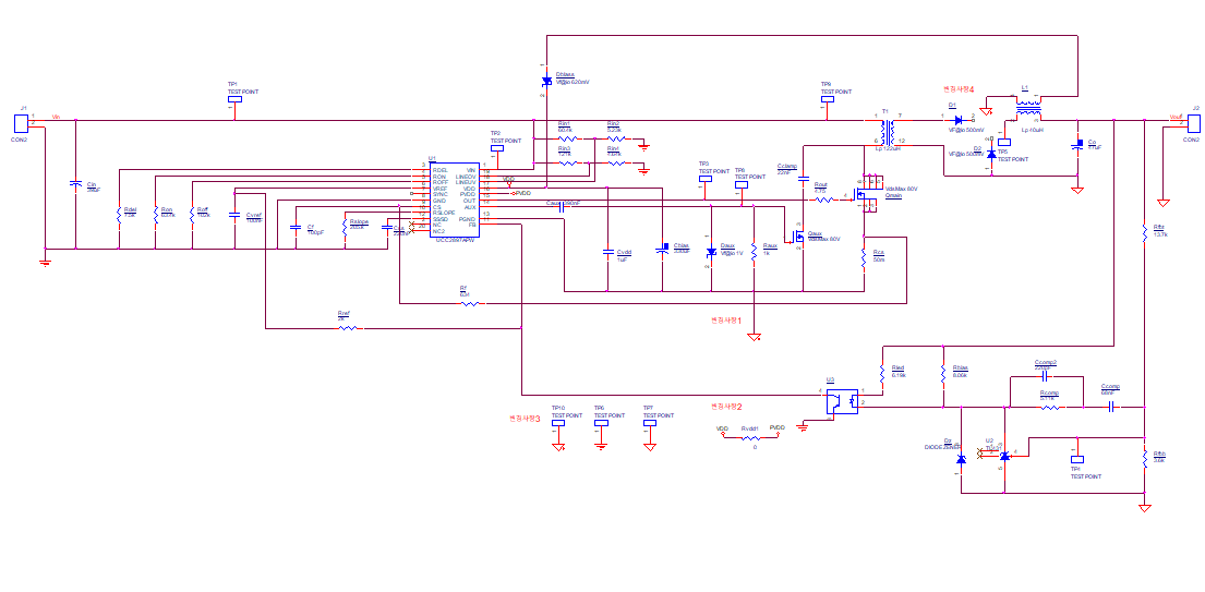
 Hello, The following is a circuit diagram of ACTIVE FORWARD CONVERTER designed based on input power 18~32V output voltage 12V,6A.
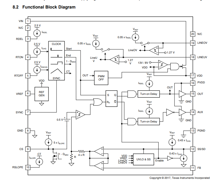
The IC used is UCC2897APW, and the open loop test is under consideration. In my opinion, the reference voltage from the SS/SD pin of the IC and the signal applied to the FB pin through the optocoupler are compared and the PWM signal is output through the internal generator. For the open loop test in the following circuit, I would like to ask if it is the correct method to review the duty by applying a signal of 2.5~4.5V to determine the duty to the FB pin.
