This thread has been locked.

If you have a related question, please click the "Ask a related question" button in the top right corner. The newly created question will be automatically linked to this question.

CSD95490Q5MC: Some application questions

Part Number: CSD95490Q5MC

Hi E2E,

Would like to know below about power stage:

1. Is there any power sequnece requirement for REFIN(~1.7V), VDD(5V), PVDD(5V) and VIN(12V)?

2. How can host device(such as controller) judge which fault type it is, among OTP and other faults? I see all of them will behave to pull up TAO pin to 3.3V.

3. When powered on, how will TAO pin behave? From 0V to room temperature calcualted voltage?

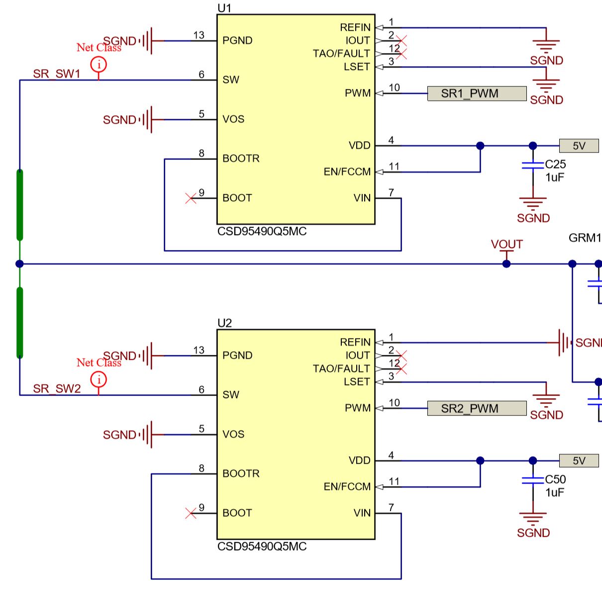
4. If you see from reference design --- PMP22519, CSD9k power stage is used in LLC topology as SR. 

As what I learned, IOUT is designed for buck topology operation, which means it will emulate buck inductor current, but in LLC, the current flowing through SR is sine-wave, so IOUT cannot correctly output sine-wave, right?

  • Hi Yi,

    Thank you for your interest. Please check my response as below:

    1. For power up sequence, we suggest to provide 3.3V/5V first, then enable power stage, then 12VIN. Once all ready, we can start with  soft-start routine to prevent inrush current. Since usually VDD and PVDD are provided from same 5V they will be powered together.

    2. The controller wont be able to distinguish the fault type. But some faults are latched fault such as over-current the TAO will always be high until fault reset, while some faults are non-latched fault such as over-temperature, the fault will be cleared once temperature dropped back to normal range.

    3. During power-up, the TAO will be released from 0V to 0.8V(if room temp) if no fault.

    4.Yes, you are correct. Iout cannot generate sine-output. You probably will see triangle shape current signal.

    Best,

    Qingquan

  • Thanks for your answer, but still unclear about this item: For the first question comment, how to understand "start with  soft-start routine to prevent inrush current?"

    When power stage is not powered by 5V, internal FETs are both off; When it is powered on by 5V, before controllers can send out specific H/L PWM, tri-state PWM also makes both internal FETs off.

    If 12V is ready first, prior to 5V, what's the difference between these two sequence? Because in these two conditions, HS and LS FETs will behave the same, both off.

  • Hi Yi,

    For different controller the soft-start may not be exact same, but the idea is to prevent long PWM pulse during start-up, so prevent in-rush current which may cause potential issue.

    When not powered by 5V, the internal circuitry of power stage such as fault detection/protection circuitry is not ready. We prefer to have power stage ready before operation.

    Best,

    Qingquan

  • Hi Qingquan,

    I have found that if DRMOS is powered prior to controller(only 5V is given, 3.3V is not powered), the REFIN will be charged to much a higher voltage(actually the value depends on REF internal circuit inside different vendor's controller), for example, 2.5V. If totally open, it should be 3.3V due to 4uA current source inside TI CSD9k.

    The question is, do you have identified some risks here especially for REFIN, if 5V is prior to 3.3V?

    In my analysis, once 3.3V is ready, REFIN will slowly drop from e.g. 2.5V to normal operation value e.g. 1.5V biased by controller. Will CSD9k work normally to report IOUT when REFIN varies? 

  • Hi Yi,

    You are correct, 3.3V should be provided before 5V if external REFIN voltage is supplied from 3.3V.

    The normal power up sequence should be: 3.3V -> 5V -> PS_EN -> 12V -> VR-EN.

    Best,

    Qingquan