Hi
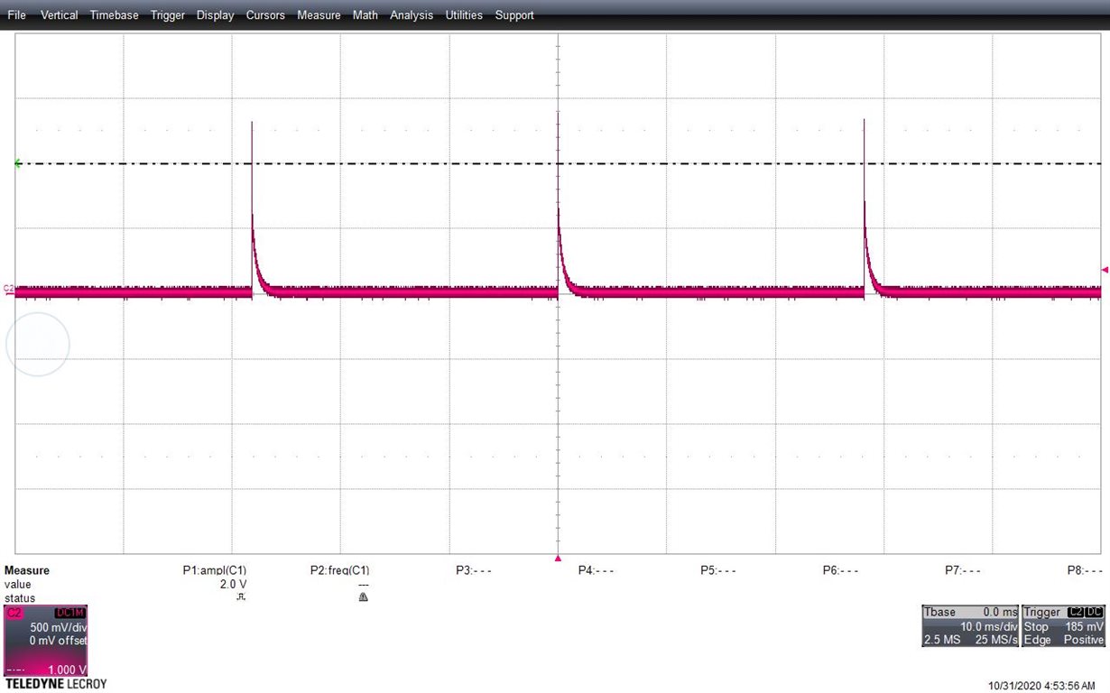
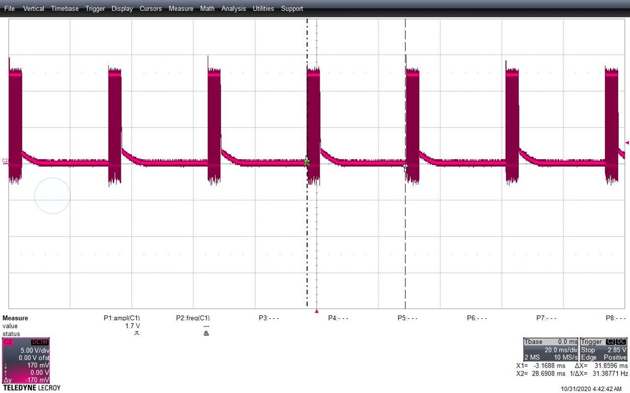
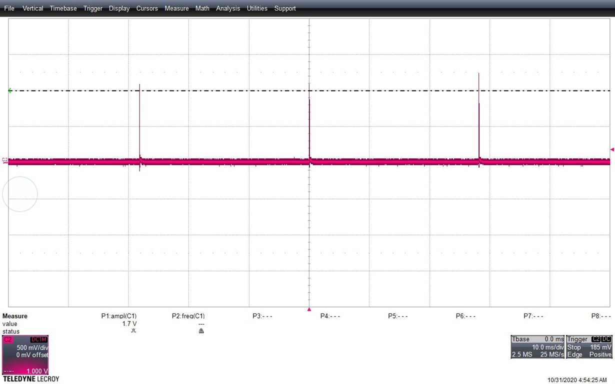
I am using TPS543c20rvft. But the output is showing strange response ie no output . I have attached the plots and schematic.


This thread has been locked.
If you have a related question, please click the "Ask a related question" button in the top right corner. The newly created question will be automatically linked to this question.
Hi
I am using TPS543c20rvft. But the output is showing strange response ie no output . I have attached the plots and schematic.


Hi,
We are looking into this. Will respond to you on Monday.
Thanks,
Lishuang
The attached schematic does not show any connection between the output voltage (VCC_0V95) and the feedback sense RSP/RSN
With a target output voltage of 0.95V and waveforms showing the output voltage exceeding 1.5V, I have a couple of theories:
1) The RSP / RSN remote sense is not connected to the output voltage and the start-up is tripping over current as the loop tries to bring the RSP voltage up, but it can not because it is not connected to the output.
2) The RSP / RSN remote sense is connected to the output, but the connection is far enough away from the local power generation that the control loop is unstable, the output is overshooting, triggering Over Voltage Protection (OVP) and shutting the converter off.
First: Check the RSP voltage during a start-up attempt.
If RSP is tracking VOUT, this is likely a lag and stability issue and we'll need to understand what else is on the VCC_0V95 net and how the RSP/RSN nets tie into them to help.
If RSP is not tracking VOUT, RSP will need to be connected to RSN to provide a regulation feedback.
Dear Sir
Thanks for the suggestion.
In the sch, Sense pin is connected to FPGA sense pins. I tried to monitor the sense pin coming from FPGA, because of device datasheet, it is not generating any sense output as current consumption is less. So I shorted sense to output 0.95V and device loop is stable now.
Thank you very much for the valuable input.
]
Regards
Vikas Kumar
BEL, Bangalore