This thread has been locked.

If you have a related question, please click the "Ask a related question" button in the top right corner. The newly created question will be automatically linked to this question.

TPS53355: Saw wave ripple at output when no load

Part Number: TPS53355

Hi;

I layouted a tps53355 dcdc board, output is 1.0V/25A, it seemed working fine. But I found when there is no load (output open circuit), the output voltage had a saw wave ripple with Vpp=18mv and period 13ms. I post the waveforms here. Please help me.

THX a lot!

Donald

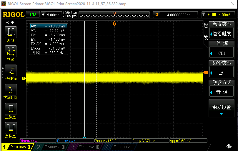
fig1: output without load
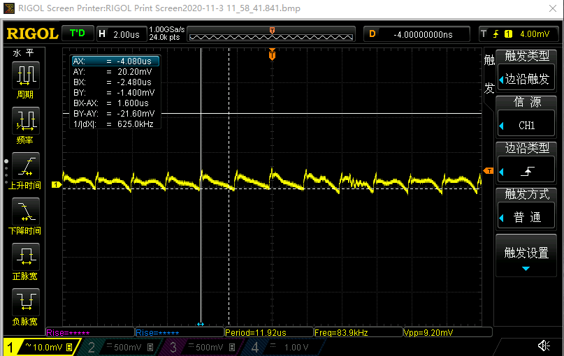
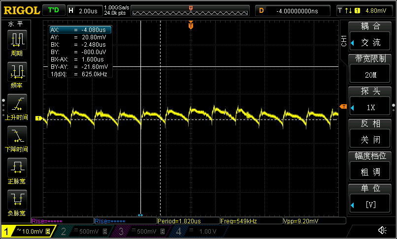
fig2: with 25A load

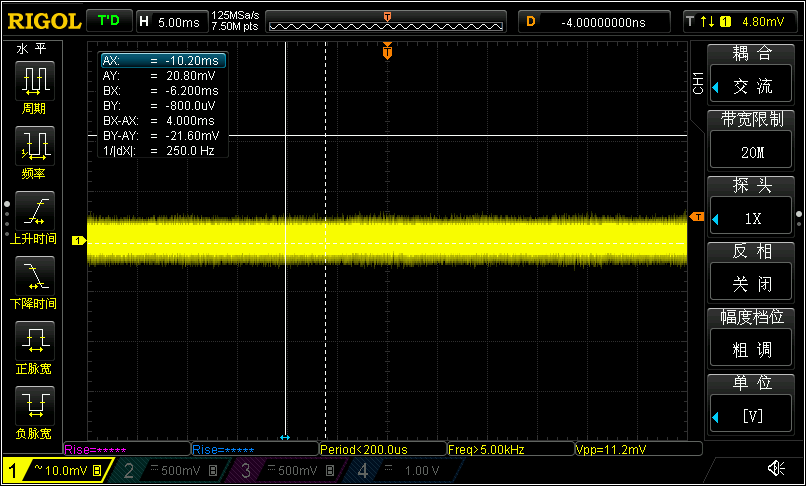
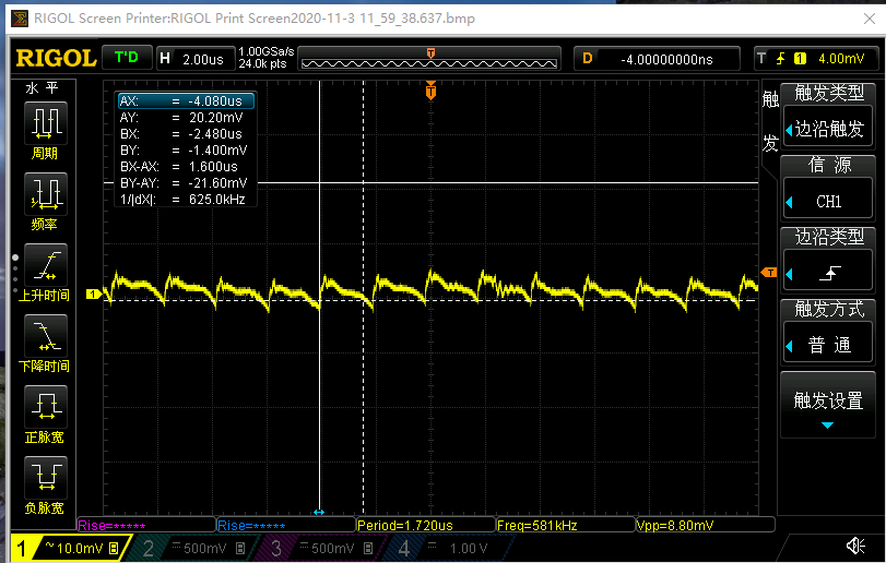
fig3: with 25A load, zoom in
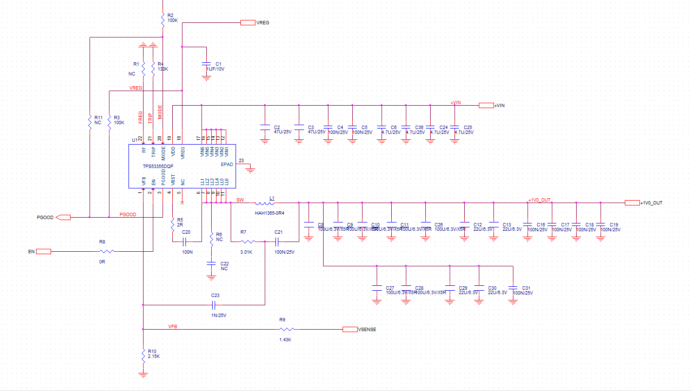
schematic:

  • Hi,

    We are looking into this. Will respond to you on Monday.

    Thanks,

    Lishuang

  • Hi


    What you are seeing looks normal. The TPS53355 has Forced Continuous Conduction Mode (FCCM) and Auto Skip Eco-mode operation options. Do you have your Mode resistor R2 connected to GND?

    That will put the device in Auto Skip mode where the switching frequency will be reduced at light loads to improve light-load efficiency, but the tradeoff is that there will be slightly higher output ripple. If you want to maintain constant switching frequency down to no load conditions, you will need to use FCCM operation by tying the Mode resistor to PGOOD as noted in Table 3 on p.20 of the datasheet.

    Regards,
    Kris

  •  

    What you are seeing is the TPS53355's powers-saving "Autoskip" mode reducing the switching frequency at very light load.  To reduce the switching frequency and associate power loss, the TPS53355 is turning off the low-side FET when it detects near zero current, emulating a diode and preventing negative current from building up in the inductor.  This reduces the switching frequency because it takes longer for the output voltage to decay back to the reference voltage when there is no current flowing out of the output capacitor through the inductor and the only discharge of the output capacitor is the feedback divider and the load current.

    The switching frequency in Auto-skip at light load is Icrit / Iout x Fsw(nom)  where:

    Icrit is the critical conduction current in the inductor, where the valley current just reaches zero.  It is half of the peak to peak inductor ripple current.

    Iout is the current load current

    Fsw(nom) is the nominal switching frequency under load currents greater than Icrit

    The ripple voltage on the output is higher in this auto-skip mode than under higher loads because in Continuous Conduction Mode, half of the inductor current ripple is positive with respect to the load current while half of the inductor ripple is negative with respect to the load current.  In Discontinuous Conduction Mode, the load current is less than 1/2 of the peak to peak inductor ripple current, so more than half of the inductor ripple is positive with respect to the load current.  In the extreme no-load case the entire inductor ripple pulse is positive with respect to the load current and the current pulse into the output capacitor has twice the amplitude and twice the base, resulting in 2x the ripple voltage.

    If your design can not tolerate the higher ripple / slower switching frequency from Auto-skip mode, you can disable Autoskip and use Forced Continuous Conduction Current (FCCM) by connecting the MODE resistor to PGOOD instead of AGND.

  • Hi;

    Yes, you are all right. When I switch to FCCM mode, everything is OK. Thank you very much!

    No load:

    No load zoom in:

     25A load: