This thread has been locked.

If you have a related question, please click the "Ask a related question" button in the top right corner. The newly created question will be automatically linked to this question.

BQ24610: My design gets very hot and stops working.

Part Number: BQ24610

Hello, 

I'm using a BQ24610 in one designed PCB in order to charge a 18V Li-ion (5cells) 4Ah battery. Maximum charged, V = 21V. 

The configuration is the following:

V_ISET1 =  0.07V (Ichg = 0.35A)

V_ISET2 = 0.3V (Iprechg = 0.3A)

V_ACSET = 0.07V (Iadp = 0.35A)

Then, the charging current is 0.35A more or less. My input voltage is 24V, the power dissipation and temperature calculation is the following: 

Pd = (Vin - Vout) * I = (24V - 21V) * 0.35A = 1.05W

The equation assumed to be valid for calculating juntion temperature from R0jA is: 

Tj = Ta + (RoJA * Pd) -> Tj = Ta + 43 ºC/W * 1.05W -> Tj = Ta + 45.15 ºC


As, Tj is 125 ºC (recommended) or 155ºC (maximum). Then the Ta could be: 

Ta = 125ºC-45.15ºC = 79.85 ºC. This is the maximum Ta that can support the system. 

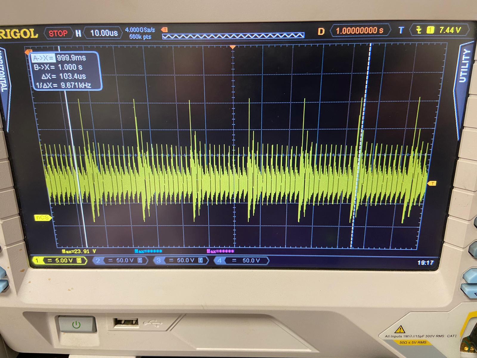
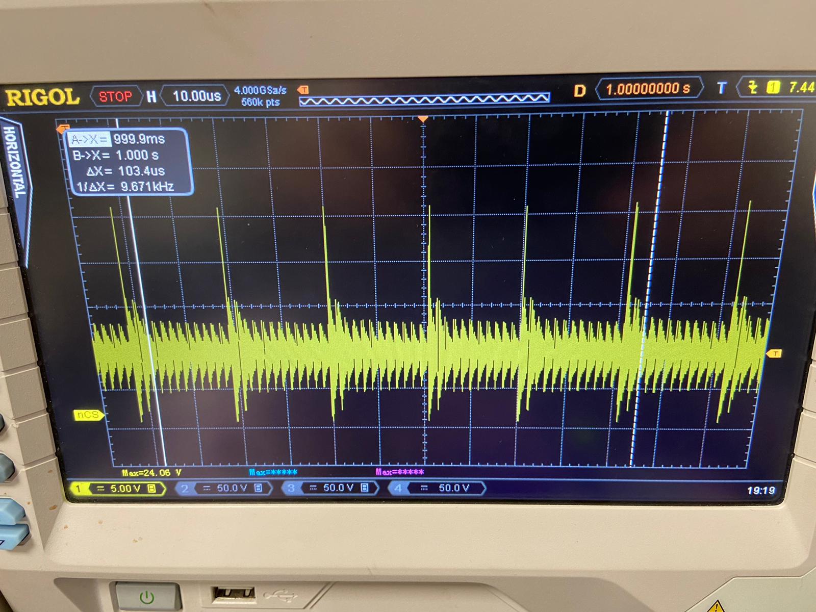
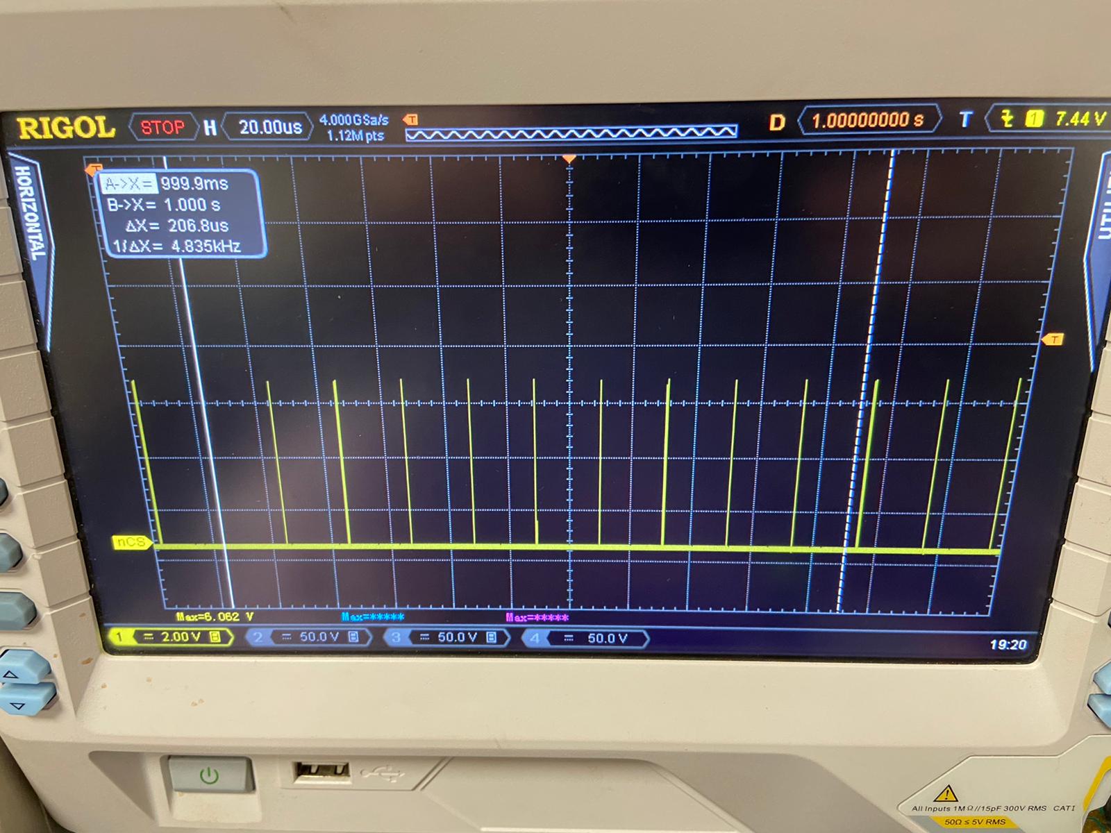
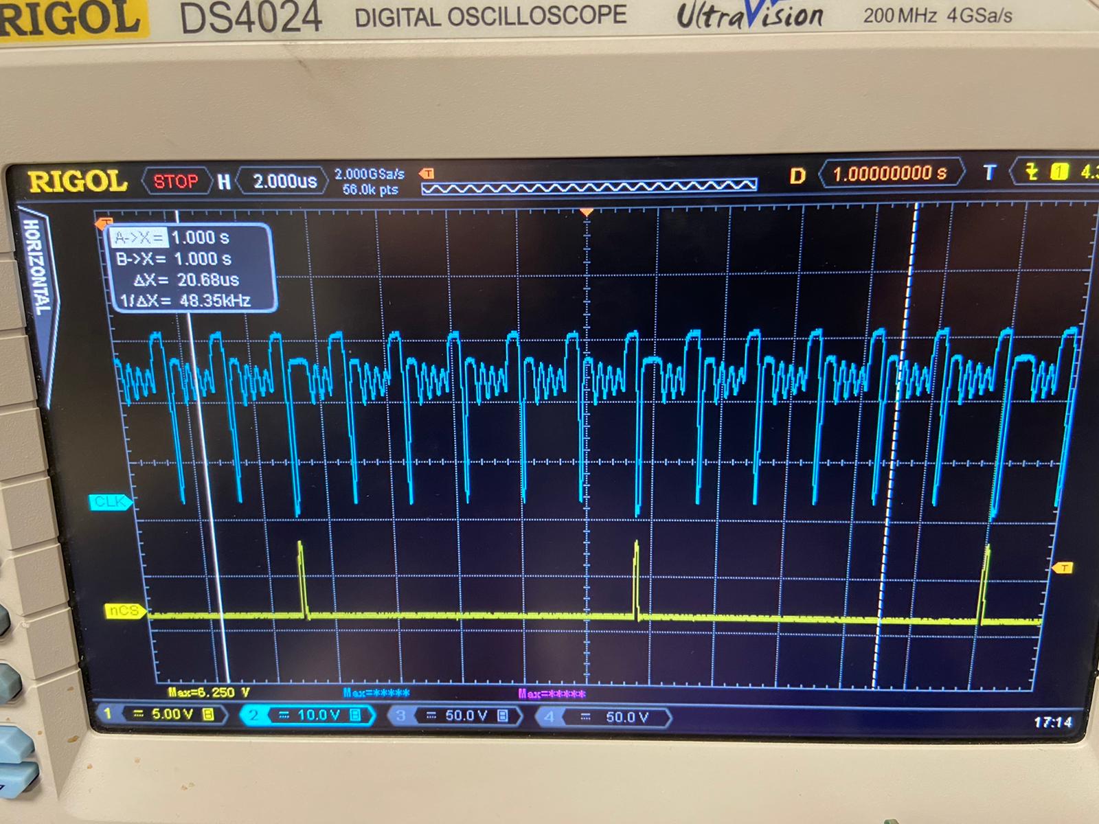
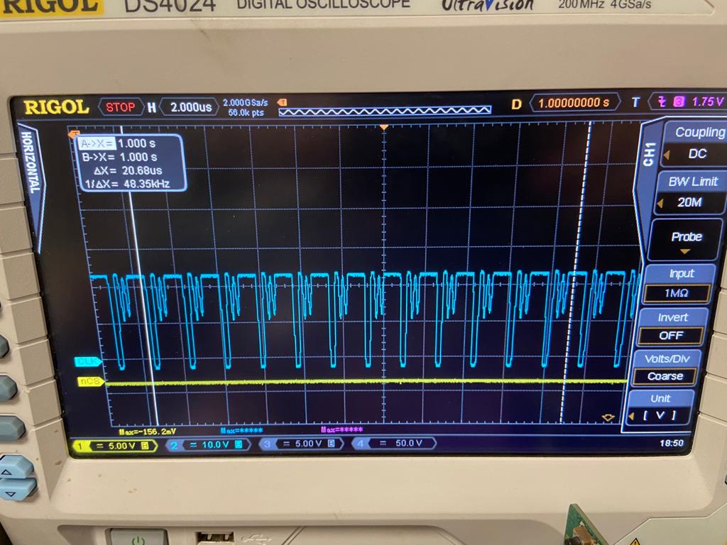
I dont' know why but the IC (bq24610) temperature is about 75 ºC. And, this is the worst part, the high side mosfet achieves the 150 ºC !!!!. I think that it has burned. 

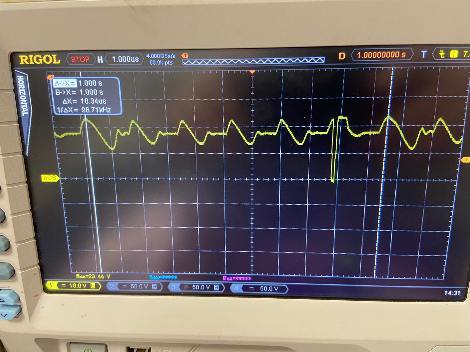
And the PH voltage, I cannot see the switching of the mosfets. 

However, the BQ24610 detects correctly the battery (STAT1 = ON, STAT2 = OFF) but the IC is not charging (maybe due to the mosfet?). 

In the output of the BQ24610 I can measure 21V more or less (when battery is not connected), this is ok no?

Where is my problem? Why am I getting these temperatures? Have I to reduce the charge current? 

Why the high side mosfet achieves 150 ºC?

Thank you very much. Any help will be very appreciated because I don't know how to proceed. 

  • Hello again, 

    Configuring the BQ24610 to charge with 50 mA current in order to not burn the PCB, I have the following HIDRV signal: 

    And the PH signal is the following: 

    Finally, the LODRV signal is the following (I think it's ok):

    What is happening with the high side MOSFET? What is wrong in the design?

    Thank you very much. 

  • Hi Luis,

       Yes, there is an issue with your switching mosfet. PH is the switch node and you should be able to see when HIDRV and LODRV are driven correctly. (Figure 4 and 5 of datasheet). Most likely the issue is with the layout of the external switching FET. Layout is also most likely contributing to the heat increase of your switching MOSFETs as you need to ensure there are vias for heat dissipation. 

  • Hello Kedar, 

    Can I improve this behaviour doing some modification or something? I have a 1KOhm series resistor to the gate of the MOSFET.. 

    My gate trace is the following: 

    Can I solve this in some way? Some idea in order to not perform a redesign by the moment... 

    Thank you a lot. 

  • Hello again, 

    I have changed the high side gate resistor to 50 Ohms.

    High side gate (blue) and low side gate (yellow) can be seen in the following image (battery absent):

    When I connect the battery, we can see PH signal (blue) and LODR (yellow) in the following image: 

    Why I have this ringing in the HIDRV signal and the PH signal? The LODRV is OK? The frequencies don't match. When I connect the battery I don't see LODR, is always 0. Is this normal?

    Thank you. 

  • Hi Luis,

        The gate drive series resistor increases gate driver loss considerably and will contribute to heat. The downside of adding a series resistor is that it slows both turn on and turn off of he HSFET, and the benefit of reducing EMI is really only when you slow down turn on. I would recommend using a 4.7ohm resistor if you need to include a series HIDRV resistor, and there is no need for any series resistance in the LODRV path.

  • Thank you Kedar, 

    With 4.7ohm resistor in the gate of the high side MOSFET improve the temperature and the behaviour of the system. Now, the charging procedure is fine. 

    Thank you again and regards,