This thread has been locked.

If you have a related question, please click the "Ask a related question" button in the top right corner. The newly created question will be automatically linked to this question.

BQ76PL455A-Q1: Random SYS_RESET

Part Number: BQ76PL455A-Q1

Hello All,

I've encountered some problems regarding the BQ76PL455A-Q1 (further called BQ). I get a SYS_RESET fault after the device is initialized and is measuring the voltages for a while (can take between 30min and multiple hours until the error occurs).

We're using the BQ on a hardware where we can monitor between 8 to 16 cells. In the case here, I use the 14 cells version, but the behaviour was also detected on the 16 cells version.

I think the problem is software-related, so here is our regular operation procedure:

Init sequence

  1. Init the UART (uC)
  2. Init the WakeUp (uC pin, enable the pin)
  3. Send a Soft-Reset command to the BQ
  4. Wait 200ms (other initializations on the hardware)
  5. Init the BQ address (set address to 0)
  6. Init the BQ GPIO (we use GPIO Pin 4 and 5 as output, no pull)
  7. Init the BQ AUX (disable pull-up on all AUX pins)
  8. Set the BQ channels value to 14 (NCHAN)
  9. Init the COMMCONFIG register (250k, UART)
  10. Init the FO_CTRL register (only comparator OV and UV)
  11. Init the comparator OV and UV values for all channels (for all 16 cells, even when using only 14 cells)
  12. Init the DEVCONFIG register (address selected by auto-addressing, comparator hysteresis enabled, faults unlatched)
  13. Init the fault masks (mask all communication faults, mask the system reset, mask the user checksum and mask the factory checksum)
  14. Init the balancing, set CBCONFIG to 1min
  15. Update the checksum
  16. Set the STATUS register (clear STACK_FAULT_DET, COMM_CLEAR and COMM_RESET)
  17. Clear all faults

Operation sequence

  1. Set the GPIO Output (we're using two LEDs)
  2. Update checksum
  3. Enable/Disable Balancing, register CBENBL
  4. Update checksum
  5. Send CMD with the channels (cell 1 to 14, all AUX, module voltage)
  6. Read / receive the measurement results
  7. Read the FAULT_SUM register
  8. If any fault is set, read all fault registers

So after a while running the operation sequence, I receive a UV_FAULT_SUM and a SYS_FAULT_SUM in the FAULT_SUM register, retreiving the data of the fault registers I get a UV_FAULT on cells 15 and 16 (unused) and a SYS_RESET.

My guess is, that -somehow- the BQ receives a reset and thus the NCHAN is set back to the default of 16 and causing the UV fault.

So my question now is how could I determine the reset source for this behaviour? Could this be communication related? What can cause the BQ to reset, besides the soft-reset?

Thanks

Alain

  • Hi Alain,

    Thanks for the detailed info - I think you are on the right track that somewhere along the line a reset occurs resetting your mask settings. Can you double confirm and read back the NUM_CHAN setting after you do your initial settings to ensure it is set? 

    Some common ways reset can happen: 1) Holding RX or wakeup down long enough on accident 2) Communications timeout occurs - can you check these settings? 3) Sending reset command - is it possible a command in the code is sending to incorrect register? 

    Can you also probe the device RX/TX/Wakeup lines when failure occurs to see what the last command to device was?

    Thanks,

    Taylor

  • Hi Taylor,

    thanks for your reply. I can confirm, that the NCHAN register is set to 14 after the initialization (in our set-register functions, we're always read back the result and cross check). I've added also a read of the NCHAN register after we see a fault in the fault-sum register (there I saw that the NCHAN was set back to 16).

    To your suggestions:

    1) The wakeup pin is controlled by the microcontroller and is currently only set to high, but I'll check on the RX-line

    2) Communication timeout, I'll check this. Maybe there could be a situation where the communication fails

    3) The reset command is only sent at the initialization procedure, but I will also check this

    4) I'll try to probe the RX/TX/Wakeup-lines and trigger them to the fault-signal to see what the last command was (unfortunately we don't have a probe who automatically detects serial communication, but I'll try it anyways).

    I'll come back after I've checked the suggestions, this will take a while ;-)

    Best regards

    Alain

  • Hi Alain,

    Thanks for the update - please let me know your findings.

    Taylor

  • Hi Taylor,

    I think I'm on the way to find the problem:

    1) WakeUp-Pin does not change and the RX line isn't long enough on low to trigger a communication failure

    2) I couldn't find any communication issues, I've also decreased the timeout in the CTO register from 1h to 10s to increase the possibility of communication related failure, but no success here

    3) Reset command isn't sent anywhere except in the init procedure

    4) I've found a scope with digital i/o, so I could check the last commands to the BQ before the problem occurs. They were never the same, or could be repeated..

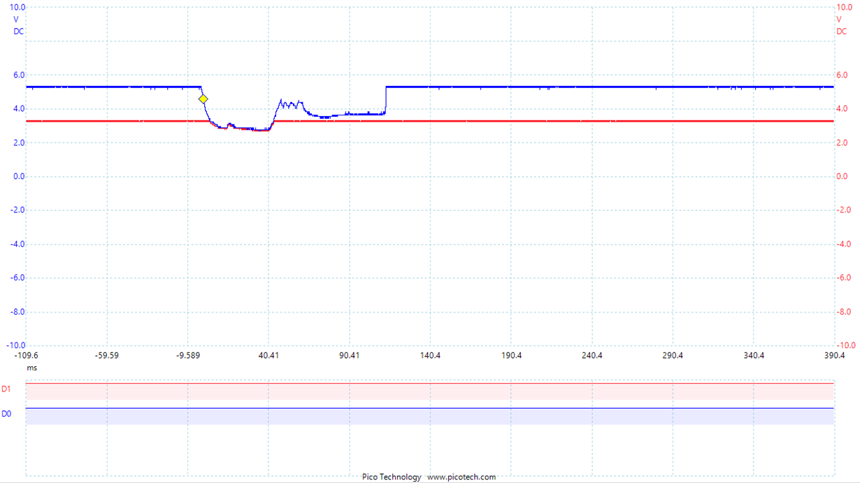
    So after the suggestions I looked a bit on the time criteria. Most of the time, the error occurs after 1 hour of running. This made me a bit suspicious, because every hour the uC is storing data on an external flash. So my next intention was to verify, if the problem occours when I'm storing data, and well I think that's the problem, look at this:

    Analog Blue is measuring the VP pin, red is the RX line (TX of the BQ).

    My guess is, that when storing data, I first need to erase some flash sectors, thus requiring more current. The power of the uC and the Flash comes from a 5V to 3.3V voltage regulator (200mA), who is powered by the VP pin. On the datasheet, the flash can need up to 100mA when erasing data.

    It looks like the voltage drop on VP only has an effect on the BQ, because the flash and the uC are behaving "normal" (no storage failure, no reset of the uC). Could this be the problem, that the BQ gets a POR-like event on the VP pin and thus a software-reset?

    Best regards

    Alain

  • Hi Alain,

    Yes that could cause a digital reset - it looks like you did a good job to diagnose this! And 100mA can be too much for this pin - can you find an alternative way to power the regulator?

    Regards,

    Taylor

  • Hi Taylor,

    thanks for your feedback. At the moment, we don't have an alternative way to power the regulator, but I've ordered a similar flash chip with less current consumption.

    Meanwhile I've run the board without the store function and it seems, that this is indeed the problem. I'll come back after I checked with the alternative flash!

    Best regards

    Alain

  • Alain,

    Great - I'm glad to hear it! 

    Taylor

  • Hi Taylor,

    just a quick update. With the new flash / reduced load current there was no problem at all. I've run a 24h test without any voltage failures or random BQ resets.

    Thanks for your help and have a great day

    Alain

  • Alain,

    Glad to hear - have a great day as well! I will close this thread.

    Regards,

    Taylor