Other Parts Discussed in Thread: BQ79616
Hi,
we are developing a new board very similar to EM1402EVM, but without the external 12V supply/battery. In our design a single cell is charged/discharged from/to the entire stack (14cells). The board work good in discharge phase, but in charge phase the temperatures of the main switch (NMOS) and the AUX/CLAMP (PMOS) rise immediately even at low charge current (<1A).
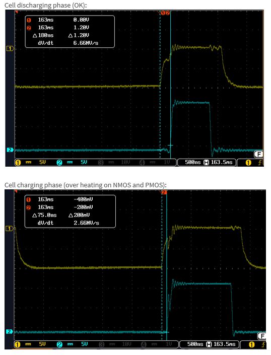
We found this waveforms on the gates of the devices, in yellow the Vgs for the PMOS and in blue the one for the NMOS.
Cell charging phase:
Cell discharging phase:
These waveforms seem correct in charging phase but incorrect in discharging phase if compared to what is reported in the EMB1499 datasheet. Below the schematic relative to the converter:
Please can anyone help me?
Regards Annibale