This thread has been locked.

If you have a related question, please click the "Ask a related question" button in the top right corner. The newly created question will be automatically linked to this question.

UC2844: Overshoot in UC2844 Driver output

Part Number: UC2844

Hi team,

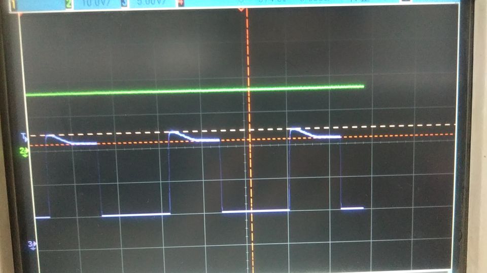
My customer is using UC2844 as a SSR flyback controller, but when they connect the output pin to MOSFET, the UCC2844 output waveform will show a drop about 2.1V, as below picture shows(peak voltage is 16.7V, steady voltage is 14.1V), can you help check why there is a voltage drop on UC2844 output? 

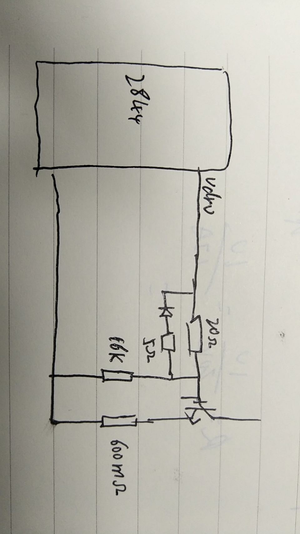
Attached issue waveform and partial schematic about driver connection with MOS.

Thank you!

Best regards 

Yunjing

  • Hi Yunjing! 

    Thank you for reaching out and for your strong support with our UC2844 device! Can you provide the model numbers for the FET and the diode shown in your drawing? The sloping seen in your waveforms is almost certainly caused by the external components shown in the partial schematic. Can the customer try removing the 5 Ohm resistor, the diode, and the 16 kOhm resistor? (They may need to tweak the 20 Ohm gate resistor value) If they do, do they still observe the sloping in the gate drive pulses? 

    Thanks again for getting in touch, I look forward to talking more soon! 

    Aidan Davidson

  • Hi Aidan,

    Thanks for your support.

    1.May I ask more detail about why you consider this  5 Ohm resistor, the diode, and the 16 kOhm resistor may cause this issue?

    2. Why VCC voltage is stable but output voltage drop?

    3. One guess from my side, do you think it possible to be a voltage drop of internal diode between VCC to OUT PIN?

    But 16.37-14.6=1.77V is too large to assume as a diode drop.

    4. Can you pls.  share the internal push pull output circuit? What is the relationship between output and VCC?

    Thank you!

    Yunjing

  • Hi Yunjing! 

    In most of our application examples (see PMP6740 for an example with a similar device) we drive the FET directly with the gate resistor. Normally a diode like the one shown is used for speeding up turn-off and improving efficiency. Would the customer be willing to share their full schematic so I can give more detailed & accurate suggestions? If they're uncomfortable with it being displayed on a public forum, please reach out to me at my email a-davidson@ti.com. 

    As for the device internals, check out the functional block diagram for the device pictured below, the UC2844 features a 1A source/sink totem-pole style output circuit. 

    Thanks again for getting in touch, I look forward to talking more soon! 

    Aidan