Other Parts Discussed in Thread: LM5170
I am simulating a design in PSpice using the LM5170-Q1 transient model.
The design is for a boost converter to generate a 60V rail for solenoid pull-in. There is a *lot* of capacitance on the HV output rail, and it will take tens of milliseconds to initially bring the rail to 60V on power up. As a result, the LM5170 is doing an early termination of the inductor charge cycle due to the cycle-by-cycle current limit. This itself is fine, as the design should meet the ongoing requirements once the system is started.
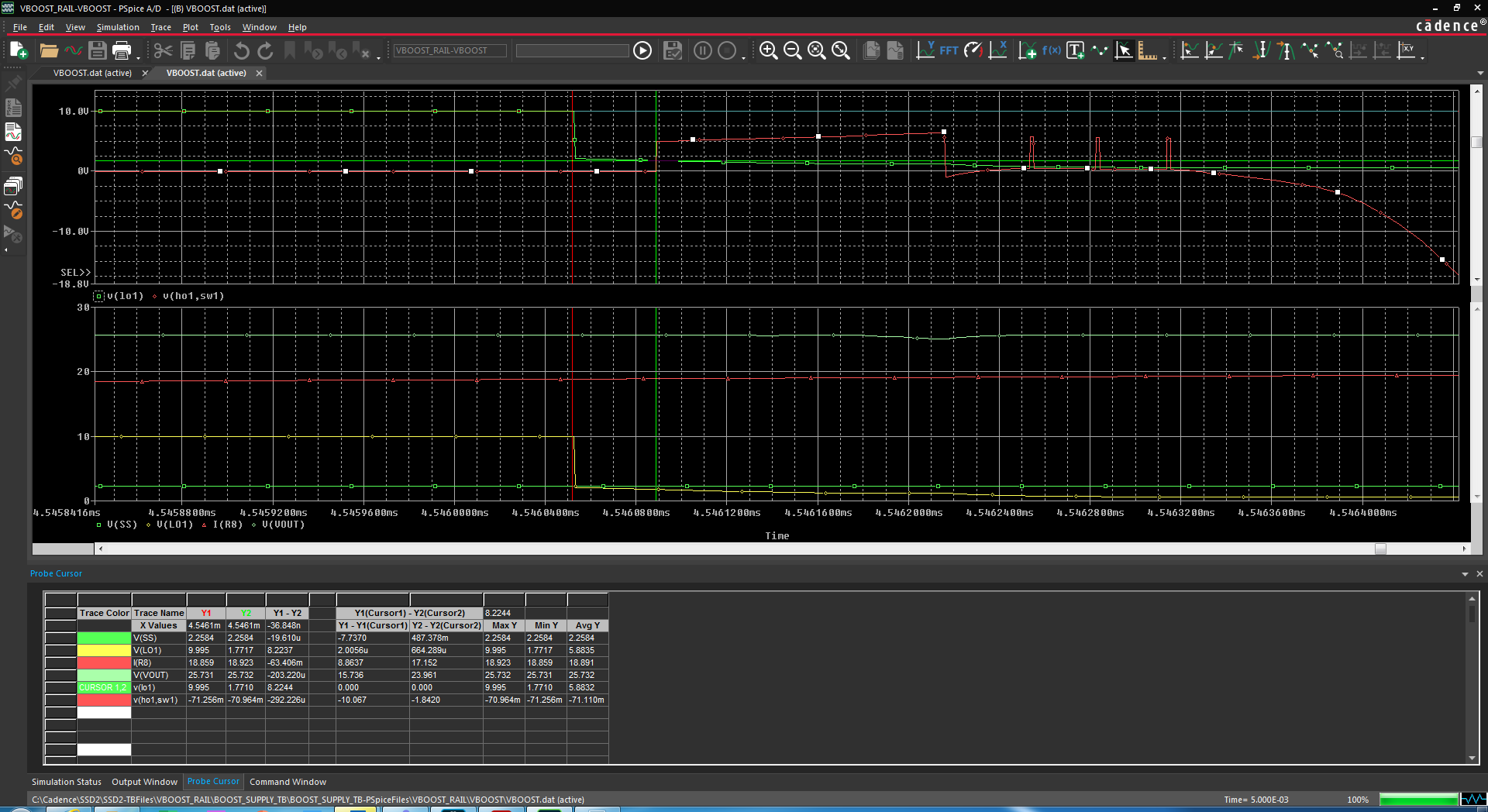
1st issue noted:The LM5170 spice model appears to be pulling HO1 down to AGND instead of SW1 when the inductor charge cycle is terminated due to the cycle-to-cycle current limit. This results in a huge negative Vgs being applied to the pass-FET, which (if this is actually how the LM5170 acts), would probably annihilate the gate insulation of the FET, especially once it gets near the 60V maximum voltage (for reference, I am using a 100V VDS MOSFET, but Vgs is rated to +/-20V maximum.)
Is this a modeling error, or is this how the part really behaves? According to the block diagrams the high side driving circuit does not show the ability to pull HO1 down to AGND (unless SW1 happens to be there); it should probably be pulling HO1 down to SW1.
2nd issue:
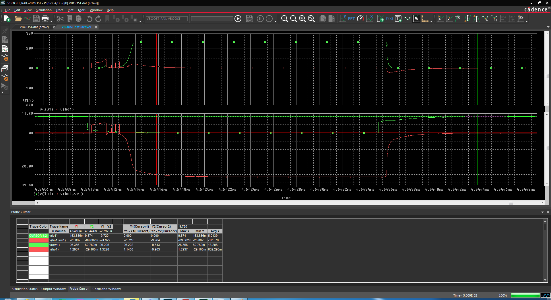
During these same current-limiting cycles, the model is ignoring the programmed deadtime set by Rdt. I am showing ~37ns of deadtime between switching off the low side driver and turning on the pass FET; this is not enough time for the low side driver to actually turn off, resulting in spectacular shoot-through as the output capacitors are shorted out. Rdt is set to 35K in these simulations which should result in ~156ns of deadtime; but that is not being enforced here.