This thread has been locked.

If you have a related question, please click the "Ask a related question" button in the top right corner. The newly created question will be automatically linked to this question.

UCC28780: Unstable peak current at 20% of power rating. Transition from ABM to LPM in the same burst packet ?

Part Number: UCC28780

Hello,

I have tuned the ACF so far at Vin = 140 Vdc.

However I can not get too much higher because I think I have a wrong behaviour of the converter.

Correct behaviour (at least, I think it is...) at 140 Vin:

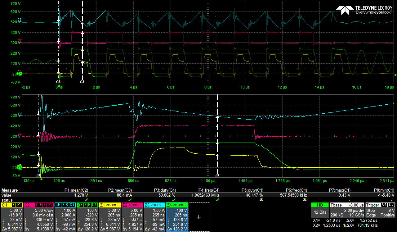
  • CH1 : Vgs of SR mosfet
  • CH2 : Vgs of high-side mosfet
  • CH3 : Current in primary of transformer
  • CH4 :Voltage at switching node

(maybe the 3rd peak current is a little bit smaller than the others)

Wrong behaviour at 200 Vin :

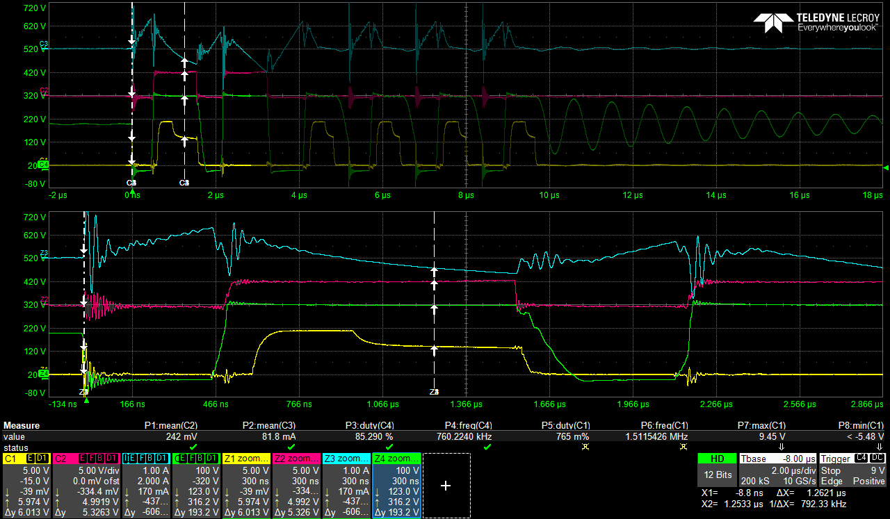
The second peak current is too low (because Ton_L is too short) and after the 2nd pulse of high-side, the controller seems to transition to valley switching (LPM). Also, synchronous rectification is lost at the second pulse.

Thank you for the help you can provide!

Best regards,

J.Ménagé

  • Hello,

    Your thread has been assigned. You should be receiving a response shortly.

  • Hello Pye,

    Thank you. Could you kindly give me a rough estimation of the time needed to answer ?

    I need it to update the planning with the rest of the tests.

    Thanks again

    Julien

  • Hi Julien,

    Some comments as below:

    1.  Different peak current at 1st and 2nd pulse , if you added a ARC circuit (a resistor + MOSFET driven by RUN)on FB pin , this circuit will pull current out of FB pin when RUN is high , usually , there is a delay for ARC circuit to impact FB current . that is why you can see a different peak current. another impact is from line compensation. the higher input voltage , higher compensation current out of CS pin , then a offset voltage generate on the resistor connected between CS pin and current sense resistor.

    2. SR missing pulse at 2nd PWMH on time . the clamp capacitor was over discharged during the first PWMH on time(Also see SR turn on time is longer than other cycles) . in the next cycle , almost all of energy was transfer to clamp capacitor other than to secondary side . so no current through SR . this is a normal behavior.

    3. Missing PWMH pulse (ABM--> LPM mode), if at 20% full load , it should not generate ABM 9 pulses and 6pulse , it looks  to me like the ABM mode is unstable , caused missing PWMH pulse . So can you share the schematic to me for reviewing . the parameters on schematic should be match with on the board.

    Thanks.

  • Hi Julien,

    Since don't get response from you for a long time , I believe it has solved your problem. if you have other questions , please create a new post.

    Thanks.

  • Thanks Jaden,

    My prototype broke (accidental short-circuit). I need to repair and I let you know.

    Thanks again.

    J.Ménagé

  • Hi Jaden,

    I have sent you the schematic with the values up to date (matching the board values).

    Thank you for your help !

    Julien