This thread has been locked.

If you have a related question, please click the "Ask a related question" button in the top right corner. The newly created question will be automatically linked to this question.

LMR50410: TI PSpice Model Question / Validation

Part Number: LMR50410

Hey team,

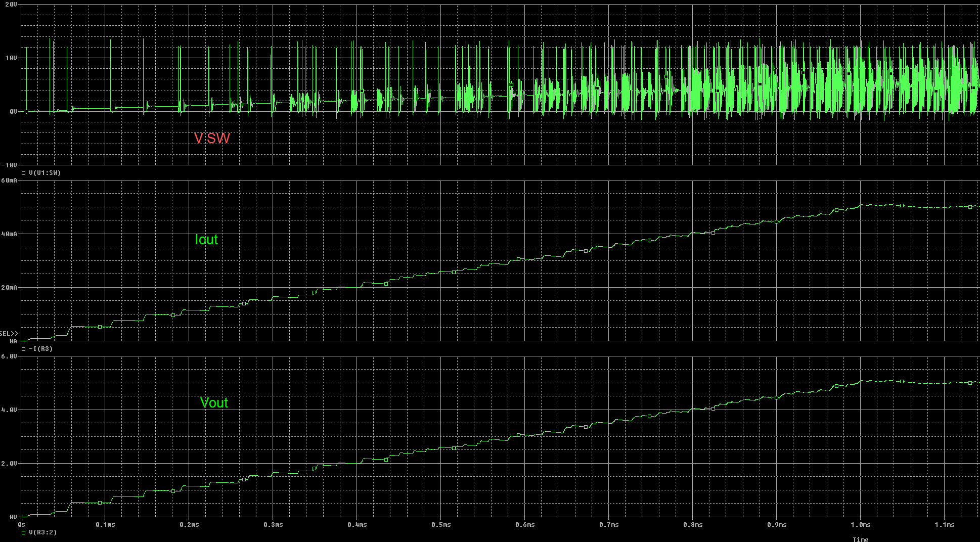
I'm looking to confirm if I'm doing this right, it's my first time using TI-pspice and I wanted to make sure I imported everything correctly and ask a quick question on loading. Attached is the output transient from spice - goal is to convert 12V down to 5V @ 1A.

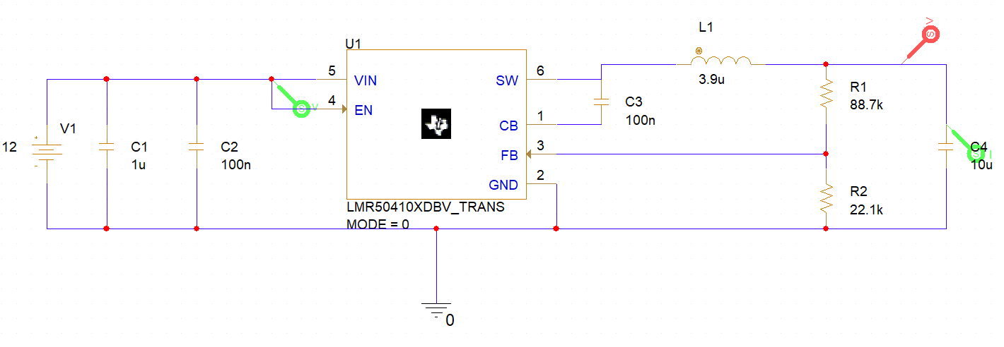
I imported the LM50410 library by following the video found here  on 3rd party model import. After doing that I recreated the webench design shown below:

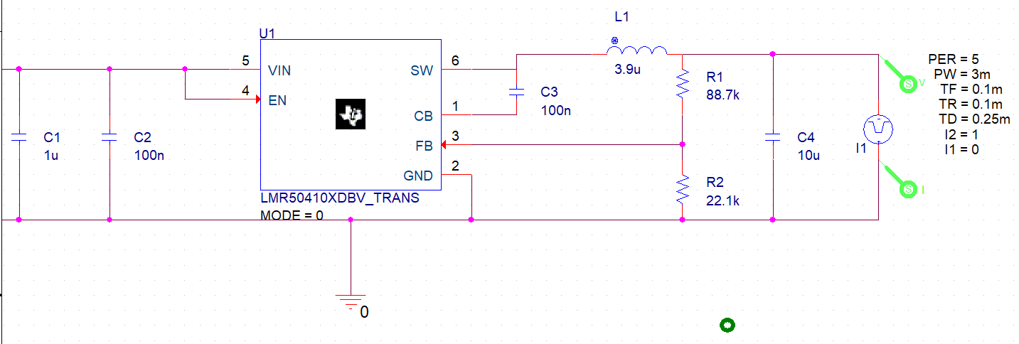
As seen by the highlighted circle, I was curious what this current load would be called on ti-pspice? When trying to simply add a large resistor to act as a load, I had some issues with getting 5V to appear correctly. Below is a picture of my design on spice:

Transient.dat

  • Not sure if the images copy and pasted correctly...

  • Hi Cameron,

    Your transient data did not appear properly for me so I'm not sure what you mean by the highlighted circle. If you take a screen capture of what you're talking about that may work better.

    If you're asking how to add something like Iout, seen in the Webench image, use the following path:

    Place->Pspice Component->Source->Current Sources->Pulse

    I would place a Pulse source if you're trying to perform a load transient.

    Let me know if this helps!

    Regards,

    Harrison Overturf

  • Man I apparently was really struggling with adding these pictures! See below for the transient showing output voltage / current over the capacitor and input voltage.

    My initial yellow circle, as you guessed, was around the current load on the output of the webench design - it didn't get readded when I saved the image and inserted it apparently. For using a current source there, would I just leave it without values and measure a voltage drop / current draw to it? Why does that simulate the load? 

    Here's the transient, I really do appreciate the help:

    Top plot is current bottom block is vout and vin

  • Hi Cameron,

    The load is effectively what your device is powering, so by using the pulse current source option, you can simulate how the device will perform when a load transient occurs. For instance, let's say you want to simulate how the LMR50410 will respond when whatever you're powering suddenly turns on/off, or put another way how would the system react to a 0% to 100% load transient.

    The pulse current source isn't really necessary if you just want to simulate how the steady state operation of the converter at full load, a simple resistor would suffice for this.

    In the above Pspice schematic you actually don't have a load, the R1 and R2 resistors are forming the feedback divider, while C4 is our output capacitor that helps keep the output voltage relatively constant and provides current to the load during the Off time.

    The pulse current parameters are required in order for this component to really do anything useful and are as follows:

    I1: starting current (OFF)

    I2: ending current (ON)

    TD: time delay, I1 will be current until TD when I2 will be current

    TR: time to rise

    TF: fall time

    PW: pulse width of I2

    PER: period

    Let me know if you have any more questions.

    Regards,

    Harrison Overturf

  • Hey Harrison,

    Again, I really appreciate the help - it's my first time trying to properly load something like this on pspice..Still running in to some issues. I actually tried loading the output with a 5M resistor previously because I thought that was the issue, but you can see the results below. I tried to setup the pulse, and confirmed that worked, but even when loaded with a resistor in series or parallel, the results still don't make sense.

    What am I doing wrong here?

  • Hi Cameron,

    Can you try running the first simulation again but replace the 5MOhm load resistor with a 10Ohm load and share the results. The 5Mohm may be causing issues.

    When you run this, try measuring the following waveforms:

    SW voltage, load current, output voltage.

    Thanks,

    Harrison Overturf

  • Hey Harrison,

    That fixed the problem - why does a smaller resistor act as a better model for this situation? Also any thoughts on what is wrong with my current source? I do want to see how the circuit reacts trying to get to 5V @ 1A current draw. I tried the reasoning that a 5 ohm load would result in a 1A current draw, but got the odd result shown in the second figure...is it poor design principle to have the device trying to operate at its max current for continuous draw?

    Note in the second figure, the top graph is current out through the resistor and the bottom graph is Vout over the resistor..

  • Hi Cameron,

    Having a smaller load resistor acts a as a more realistic load and allows the loop to work as expected by allowing the DC current inductor current to flow to the load resistor while the AC component goes to charge and output capacitor. When the 5MOhm load resistor was present, the path of least resistance for the DC inductor current was down through the FB path rather than out to the load which must have caused the model to have show the strange behavior that you witnessed.

    For your current source, try flipping it around by 180 degrees, the orientation you have it in your above schematic looks to be the wrong way.

    Have you tried downloading the model file from the LMR50410 product folder on ti.com? I was able to simulate the response of the system to a load step from 0.5A to 1A as below. If you haven't tried already, you could try downloading this model file and updating the schematic.

    Regards,

    Harrison Overturf

  • So I think what happened was pspice updated my library for all the TI parts after I tried to import this one so some odd stuff was happening. I replaced the part and reran the simulation with the current source ( which I did flip by accident because I forgot how current draw would look like from the load side) and everything is looking correct.

    One last question - any recommendations for simulation settings? It takes so long to get all the results and I've tried messing around a bit with the accuracy settings to no avail.. :( it'll be brutal if I can't get a rough estimate faster. Maybe I'll install pspice on my desktop.

  • Hi Cameron,

    Glad to hear things are working now!

    Try enabling Auto Converge under Simulation Settings-> Options -> Auto converge, this usually makes things run faster for me. 

    If you are still encountering simulation run time errors, try posting a new thread and you'll be able to speak directly with our modeling experts.

    Regards,

    Harrison Overturf