This thread has been locked.

If you have a related question, please click the "Ask a related question" button in the top right corner. The newly created question will be automatically linked to this question.

TPS24751: eFuse design parameters and Internal MOSFET SOA check

Part Number: TPS24751
Other Parts Discussed in Thread: TPS24750, TPS25982, TPS25980, TPS25750, TPS2595, TPS25947

We are currently using TPS24751 into one of our 75W PCIe ADD-IN card designs.

The design parameters are as follows

Vcc = 12V ± 8% (11.02V to 12.96V)

Current Limit set = 6.5A (actual current limit is 5.5A from specification)

Maximum power dissipation of the card = 75W (12V @ 5.5A).

PLIM = ~22W (internal MOSFET power consumption)

Maximum Output capacitance = 675uF

PLIM specification in efuse is it for Maximum power limit of the Internal MOSFET or Vout * Iout limit.?

Below are the component values selected.

SET resister

61.9

Sense resister

5

mΩ

IMON resister

1.27

kΩ

PROG resister

37.4

kΩ

Timer Capacitor

47

nF

 Below are the limits which we are getting from values chosen

Current Limit

6.5799

A

Power Limit

21.992

W

Actual Fault time of our design

6.345

mS

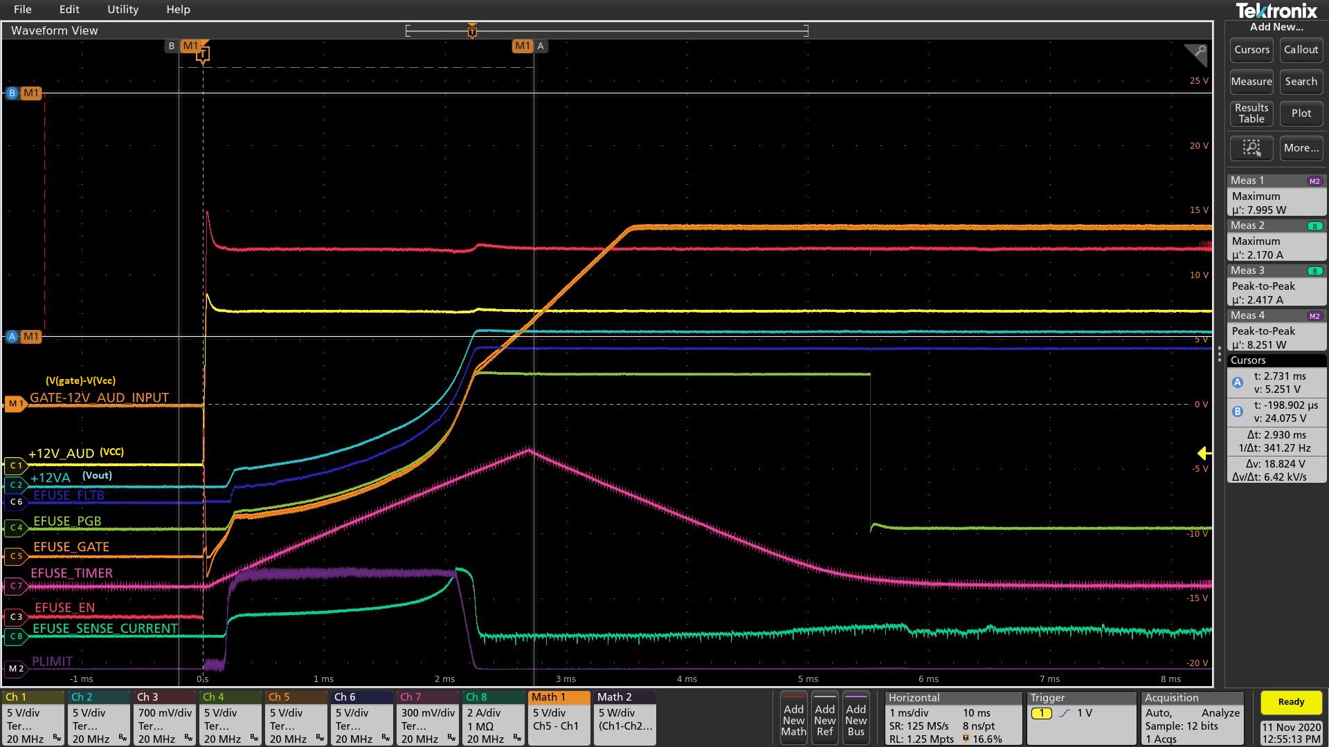
 We are using gate capacitor of 4.7nf+1K for slew rate control. This configuration is tested (Not fully, but boards are booting fine).


Now we are re-designing this to 25W PCIe card. Below are the specifications.

Vcc = 12V ± 8% (11.02V to 12.96V)

Current Limit set = 2.5A (actual current limit is 2.1A from specification)

Maximum power dissipation of the card = 25W (12V @ 2.1A).

PLIM = ~22W (internal MOSFET power consumption)

Maximum Output capacitance = 675uF

SET resister

51.1

Sense resister

10

mΩ

IMON resister

1.37

kΩ

PROG resister

31.6

kΩ

Timer Capacitor

56

nF


Below are the limits which we are getting from values chosen

Current Limit

2.5177

A

Power Limit

22.008

W

Actual Fault time of our design

7.56

mS


I have few questions on the design.

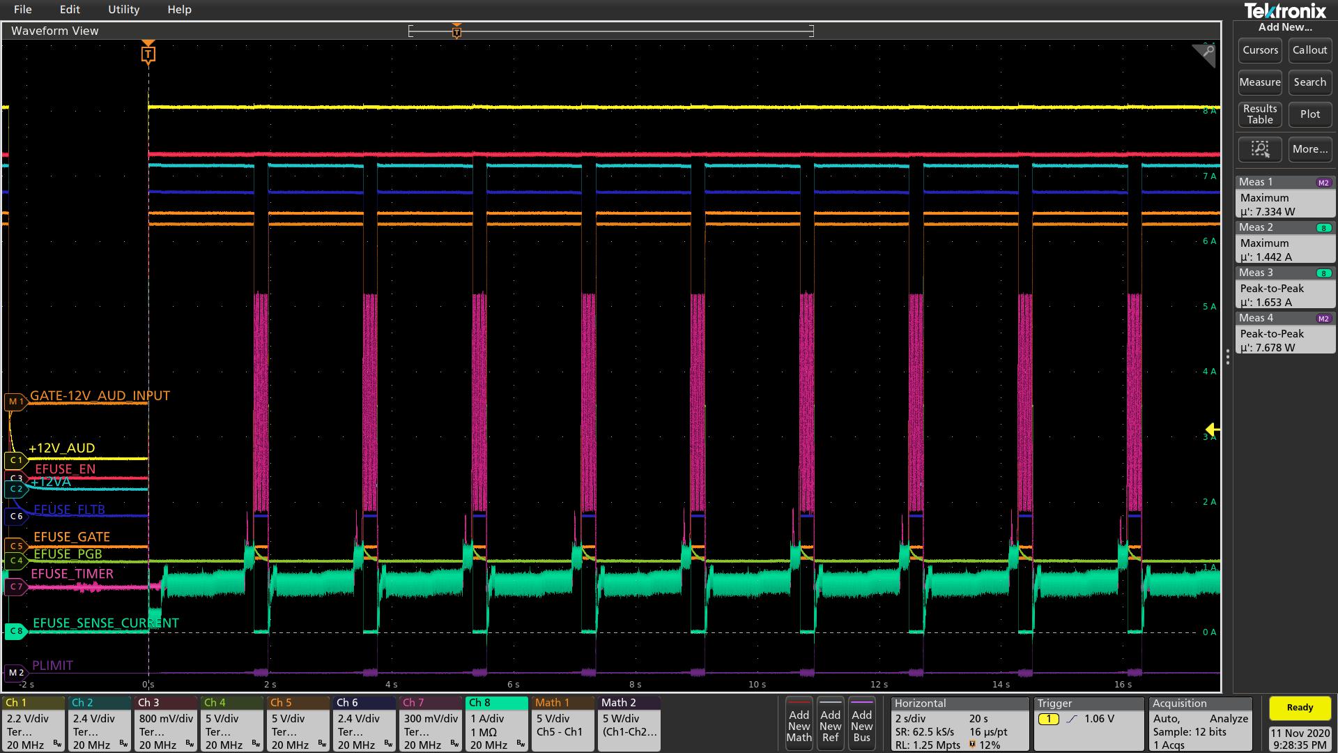
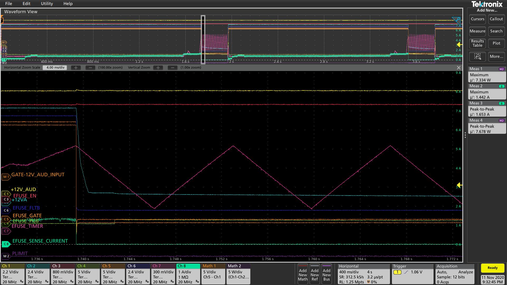
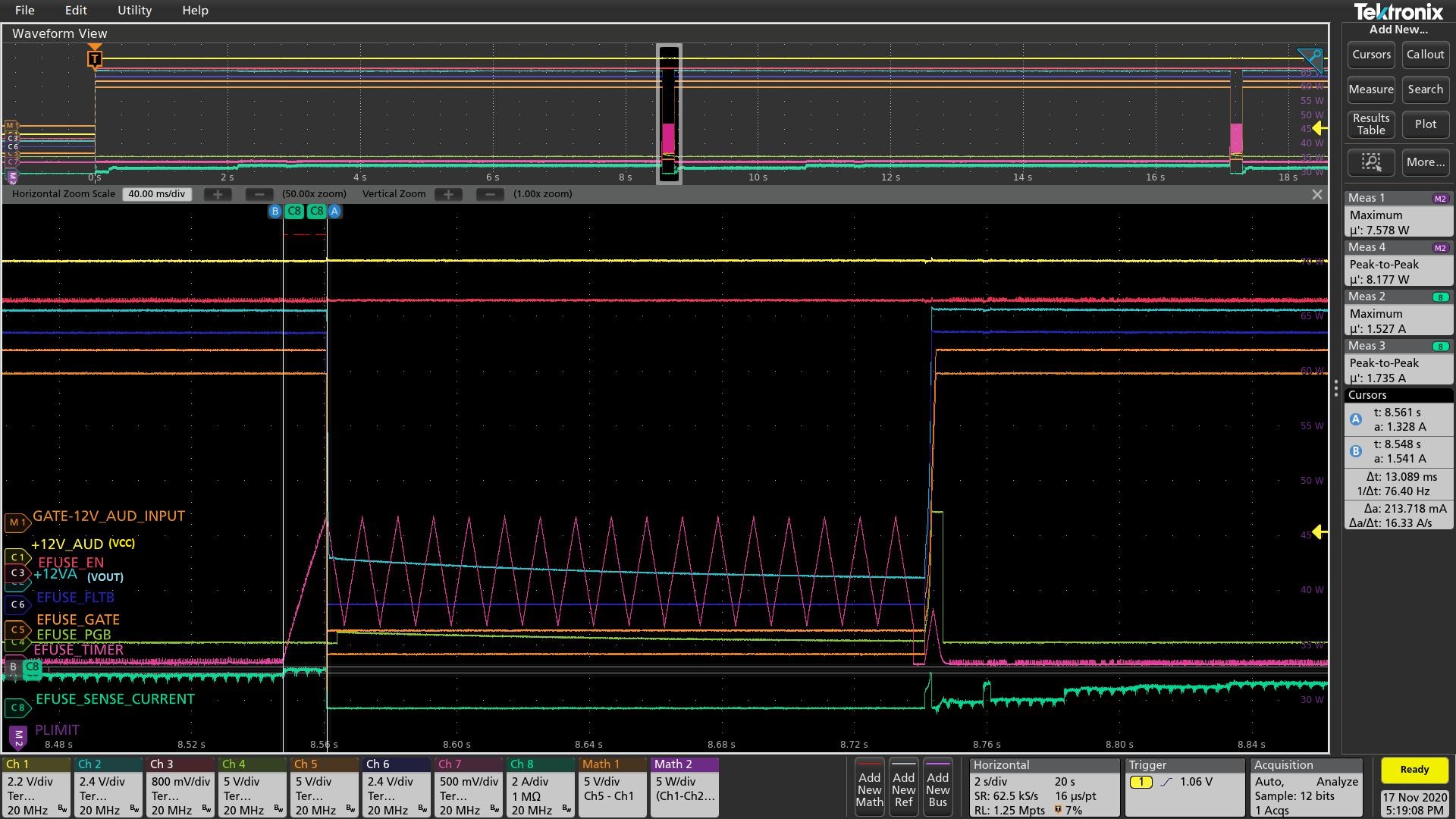
1. In the 25W card (redesign) always (including inrush) our max current should be ~2.1A. Is the values calculated are fine to have this current limit.

2.With out gate capacitor, with PLIM functionality whether the max current during inrush will exceed 2.1A.

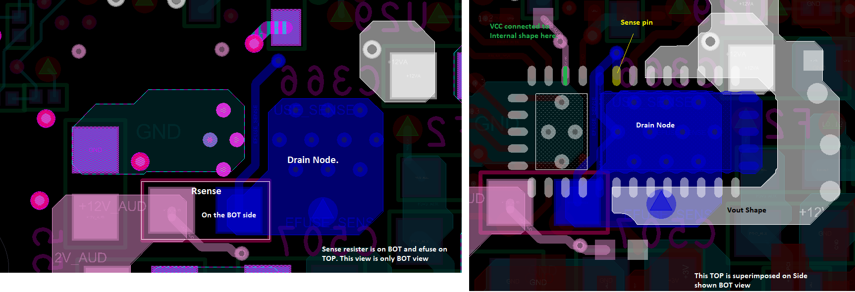
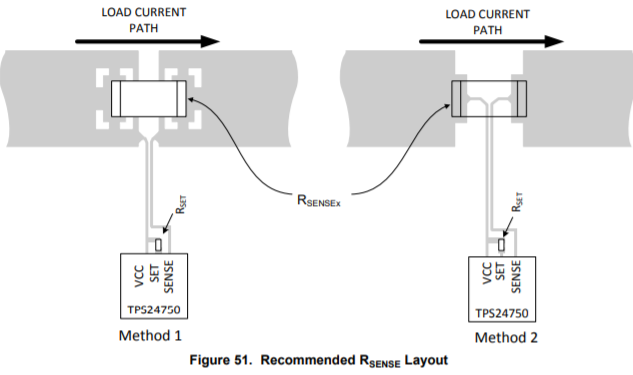
3. If use Rsense as 5mΩ as like old design the Vsns is ~10mV(@2A Iout) which is close to lower limit – Is it OK, or I can use 10mΩ.


  • Hi,

    Thanks for reaching out to us. 

    For your calculations on TPS2475, you can use design calculator available at  Meanwhile, I would like to propose a better part for your application. 

    TPS25982 and TPS25980 are next generation parts of TPS24751. The new generation devices integrate the sense resistor, have additional features and come in a more compact package 4mmx 4mm  versus the TPS24750 which is in a 7mm x 3.5mm + external Shunt resistor. 

    Below is a comparison table between TPS25982 and TPS25750. Do let us know your  thoughts on TPS25982.

    Since your load current is less than 4A, you can also have a look at TPS2595. 

    Material

    TPS25982

    TPS24750

    Min VIN (V)

    2.7

    2.5

    Max VIN (V)

    24

    18

    Abs Max VIN (V)

    30

    30

    Iq

    800 uA

    1.4mA

    RON (mΩ) @ 25C TJ

    2.7

    3

    RON (mΩ) @ 125C TJ

    4.5 (max)

    6 (max)

    Current sense

    Internal

    External

    IMON accuracy

    1.5% @ 25C, 3%

    Across temperature

    (3A < Iout < 15A)

    10% (Range defined by ext Rsense)

    Overcurrent Response

    ILIM/CB option

    CB

    Prog OC timer for transients

    Yes

    No

    Min Current Limit (A)

    2

    0.01

    Max Current Limit (A)

    15

    12

    Current Limit Accuracy (%)

    +/-8% (5A < Ilim < 15A), @ 25C

    +/-13% (5A < Ilim < 15A) Across temperature

    +/-10%

    Fast trip threshold

    Adj (2.1xILIM)

    N/A

    Fast trip response time

    250ns

    200ns

    Prog. UVLO

    Yes

    No

    OVLO

    Options for Fixed Thresholds

    /No OVLO

    Adj

    Output Discharge

    No

    No

    Power Good output

    Yes

    Yes

    Dedicated Fault Indication

    No

    Yes

    Load start Handshake Timer

    Yes (LDSTRT)

    No

    Prog. Auto-retry delay

    Yes

    No

    Prog. Auto-retry count

    Yes

    No

    UL Recognized

    Yes 

    No

    Package

    QFN-24 , 4x4

    VQFN-36, 3.5 x 7

  • Hi Praveen,

    We came ahead in design cycle so, that layout changes are seldom taken and BOM changes are OK.

    Another thing is --> we need Over voltage protection of 13-14V (Our max voltage =12+8%), these devices doesn't have Adjustable or OVP near to 13-14V.

    I have used that excel to find the values of the components.

    With out gate capacitor, with PLIM functionality alone, whether the max current during inrush will exceed 2.1A.

    Is there any simulation model available for this?

  • Hi,

    Can you please share the filled in design calculator for review. 

    You can find the PSpice model for this device in the Product Folder of the IC, link below


  • I am attaching the excel.

  • Hi,

    I am unable the download the attachment. Can you upload it again using the 'Attach File' option.

  • Hi,

    Thanks for sharing the design calculator. I will get back to you within a couple of days.

  • Hi Praveen,

    We have done few captures for earlier design. 

    SET resister

    61.9

    Sense resister

    5

    mΩ

    IMON resister

    1.27

    kΩ

    PROG resister

    37.4

    kΩ

    Timer Capacitor

    47

    nF

     Below are the limits which we are getting from values chosen

    Current Limit

    6.5799

    A

    Power Limit

    21.992

    W

    Actual Fault time of our design

    6.345

    mS

    I see maximum power limit during inrush is always ~7.8W (which is the minimum PLIM mentioned in excel)

    We have configured PLIM to ~22W using PROG resister (37.4k), why PLIM is reduced to ~7.8W in inrush?

  • Hi,

    The design looks good to me with the values shared in the design calculator. The actual inrush current is around 2 A which is as per your requirement of <2.1A.

    What is the Gate capacitance on the  board for the condition when you have tested and shared the waveforms ? Please share the design calculator with filled in parameters as per your actual test conditions. 

  • Hi Praveen,

    We have tested with new values also.

    SET resister 51.1Ω

    Sense resister 10mΩ

    IMON resister 1.37kΩ

    PROG resister 31.6kΩ

    Timer Capacitor 56nF

    I am hitting current limit at ~1.34A and Vout is going down for 16 cycles and rising again.

    putting a snapshot of the capture.

    I have some doubts on why current limit is hitting at different point than programmed. I will get myself cleared and get back to you.

    About query on gate capacitance, we have an option of 4.7nF on design but currently we have de-populated it for testing purposes. Once all the values are set, i want to populate gate capacitance.

  • Hi,

    What are the test conditions at which you have captured the waveforms ? Is it during startup or over load conditions ?

    With the below configuration values, the Actual I-limit value = 2.5 A and the Actual power limit for Rprog = 9.9 W. 

    • SET resister 51.1Ω
    • Sense resister 10mΩ
    • IMON resister 1.37kΩ
    • PROG resister 31.6kΩ
    • Timer Capacitor 56nF

    Is the total output capacitance in your system  = 675 uF ?

  • Hi Praveen,

    Regarding the measurement conditions,

    First capture Trigger point shows the Power ON, after Power ON ~2seconds there is a current rise of ~1.34A where i believe TPS24751 is sensing current limit and starting timer to rise and after timer rised to 1.35V Output,Gate all are driven LOW and after 16 cycles they are restarted.

    same process going on.

    The design values which above captures(PLIM=22W,ILIM=2.5A) were taken are with

    • SET resister 51.1Ω
    • Sense resister 10mΩ
    • IMON resister 1.37kΩ
    • PROG resister 14.3kΩ
    • Timer Capacitor 56nF
    • No dvt/dt control

    What we are seeing is even though current limit is configured for ~2.5A, actually current limit is triggering (Timer voltage is raising) @ 1.34A.

    We have tested for another configuration: PLIM = 22W, ILIM = 2.7A;

    • SET resister 51.1Ω
    • Sense resister 10mΩ
    • IMON resister 1.27kΩ
    • PROG resister 15.4kΩ
    • Timer Capacitor 56nF
    • No dvt/dt control

    Here, same behavior is happening @ ~1.54A (instead of 1.34A as for 2.5A ILIM case as above).

    attaching capture for the same.

  • Hi,

    Can you share the layout for review ?

  • Hi Praveen,

    When the design is created (parameters ILIM #6.5A)at that time Layout is reviewed by ti.

    We are getting the values from design calculator for different configurations (ILIM - 2.5A,2.7A,3.0A) , but testing results show current limit triggering for lower currents than programmed.

    Don't know the reason.

    Do you see any issue with Rsense of 10mohms.

    Our configuration is

    ILIM : 2.7A, PLIM : 22W,

    Currently we are using gate capacitor of 4.7nf.

    Suggest the working values, we can test it and update.

    You can suggest with and without gate capacitor.

  • Hi,

    To obtain Current limit = 2.7 A and Power limit = 22 W, for Vin = 12V and Cout = 675 uF you can use the following values,

    Rsense = 10 mohms, Rset = 51.1 ohms, Rimon = 1.27 kohms, Rprog = 15.3 kohms

    The current limit accuracy depends on 

    • Rsense, Rset and Rimon values and their accuracy
    • Layout at Rsense 

    Please review the above to obtain good current limit accuracy. 

  • Hi Praveen,

    These values are same as what we took. 

    1. Can we use Timer capacitor as 56nF?

    Below is the layout, I am not sure how much it will be clear.

    In the Layout Sense resister is placed on the BOTTOM side and TPS24751 is placed on TOP Side.

    In the image shared, Left side Part Only BOTTOM layer is shown and then in the right part TOP portion is overlaid on BOTTOM view.

  • Hi,

    I would recommend you to try the following,

    • Use the same configuration, IC and Components on TI EVM and test the circuit on EVM.
      • This will tell us if there is an issue with the IC/ components or your layout
    • Use resistive load while testing current limit behavior of IC. Using e-Load, especially in CC mode can cause problems
    • Replace the IC on your board with a new IC and test the same.

  • Hi Praveen,

    We don't have EVM to test locally. i will check on the purchase options which will take time.

    I am seeing something can be derived with whatever data we have from the test results and Layout perspective.

    From the values you sent, I am sure that values used for testing are correct.

    From the layout side, i see our layout different from EVM layout -> But its difficult to me to access the % of error from deviation in the layout.

    One more thing " In Layout Rsense shown as single resister, because we don't have 10mOhms in hand, we connected 2 no's of 5 mohms resisters in series with common pad in air other 2 pads to Board"

    Do you see directly any evident problems with our layout from your experience with TPS2475x,

    or

    Previously this kind of layout also given good results.

    Currently, i didn't used any e-load/Resistive load. Board load varies from LOW to MEDIUM and then to MAX from BOOT-UP.

    Currently in from BOOT-UP until load is "LOW" no current limit is hitting TPS24751 behaves correctly, But once Load reaches to MEDIUM, current limit is hitting.

    We will test with 2.7A configuration in another board to confirm(This will clear if we have assembly issues on board (unlikely checked multiple times) or wrong values on board).

  • Hi,

    Thanks for your response. I will get back to you on this within a couple of days. 

  • Hi,

    Yes, it is very difficult to estimate the %error in current limit from the layout. 

    Soldering 2 x 5 mohms resistances in series with the common pad lifted up may not be a good practice and the amount  of solder used also contributes to the resistance and hence increases the error. 

    The tapping point of sense lines tapped from the sense resistor need to be in such a way that the sense lines are not in the current carrying path to avoid error. 

    I am not clear on your testing procedure of current limit. I would recommend you to use a resistive load to load the output gradually and find out the current limit point. 

  • Praveen,

    I agree with you on connecting 2, 5mΩ resisters in series as mentioned above.

    I will try to get 10mΩ and test it.

    On the testing procedure,

    The efuse has to work our environment, 

    To explain, Once the board is booted, board enters different power modes. for first start in "LOW" Power mode and then after some time it goes to "MEDIUM" power mode and then to "HIGH" power mode.

    Now, in our case efuse works properly in "LOW" power state, and when board enters "MEDIUM" power state efuse is triggering the current limit.

    Just nomenclature is different,

    final point is efuse is triggering at lower threshold than programmed one.

    I need a help, to get EVB it takes some time for us. 

    Can you test from your end with the values provided and confirm it works with current limit of 2.7A.

    We are thinking to change this IC to newer versions from ti next design onwards.

  • Hi,

    I would recommend you to consider using TPS25982 as the sense resistance is integrated and the over all solution is more compact, more efficient and has more features compared to that of TPS24751.

    You can order the EVM here. Also, you can contact TI sales team for support on ordering the EVM.  

    Regrading my testing recommendation using resistive load , this is to find out the exact load current/resistance at which the device reaches current limit vs the actual set threshold. I am not sure if you can find out the exact load current value at which the device reaches current limit using your load. 

  • Hi Praveen,

    Thanks for the update.

    For the next boards we are seeing alternate to replace this.

    I have 2 candidates one TPS25982 or TPS259470ARPW for next design. TPS25982 has higher ON resistance compared to TPS259470 - You have any other comments on TPS259470.

    Regarding the Load,

    I am probing the current also in a CH8, which gives us exact current (sense current). Even we test with resistive load, it should work with actual board load.

  • Hi,

    TPS25982 has much lower Rdson compared to TPS25947. The Rdson of TPS25982 is 2.7 mohms and the Rdson of TPs25947 is 28 mohms. 

  • There is a confusion.

    TPS25982 is not a choice to us because it doesn't have adjustable OVP (fixed OVP options are not in our operating range), this we discussed earlier in the post.

    If TPS25982 has adjustable OVP also, it will be really good solution.

    I was comparing TPS25942x/44x w.r.t TPS25947xx. 

  • Hi,

    Got it. Yes, your understanding is correct. Sorry if I have created any confusion. You can consider using TPS25947 for your application.