


Other Parts Discussed in Thread: OPA320, LM5141, LM5145
Hi experts!
My customer is working with the LM5117 and has some questions regarding usage of an amplifier in the current sense/feedback path.
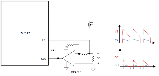
As shown in the diagram above, in order to minimize the power loss on the current sense resistor, I added additional op-amp OPA320. This works well at heavy load.
However in the light load for forced CCM operation, V1 could go negative, while my V2 will be clamped by the single-ended OPA320. I am planning to use diode emulation mode to prevent inductor current from going negative.
Therefore, my question is: how does LM5117 detect zero current? My understanding is it looks at the delta_V between CSG and CS pin, and compare with an internal threshold V_ZCD, is that correct? If so, what is the tolerance or distribution of V_ZCD, is there any possibility that V_ZCD is negative, so that the configuration with OPA320 cannot detect zero-current and enter diode-emulation mode?
Thanks in advance for your help.
Best regards,
Jim B

