A related question is a question created from another question. When the related question is created, it will be automatically linked to the original question.
If you have a related question, please click the "Ask a related question" button in the top right corner. The newly created question will be automatically linked to this question.
Please send a completed LM5116 quickstart calculator file for this design. The file is available by download from the LM5116 product folder.
Here are some comments on the schematic:
One sense resistor should be enough (and even then, 2512 is a very large package).
No need for a resistor from SW to CS (possible path for noise injection too).
Add a placeholder for a cap from CS to CSG in the unlikely case noise becomes is an issue
Add a series resistor from VOUt to VCCX in case you need to disconnect VCCX
The additional Fly-Buck circuit to generate VCCX and 5V seems excessive. Btw, this circuit only works correctly in CCM. Also, the inductor performance is no longer optimized.
Boot cap can be 0.1-0.22uF.
Snubber components seem large (1206 footprints), these usually end up compromising the power stage layout - see app note snva803. An 0603 cap and an 0805 resistor is typically adequate.
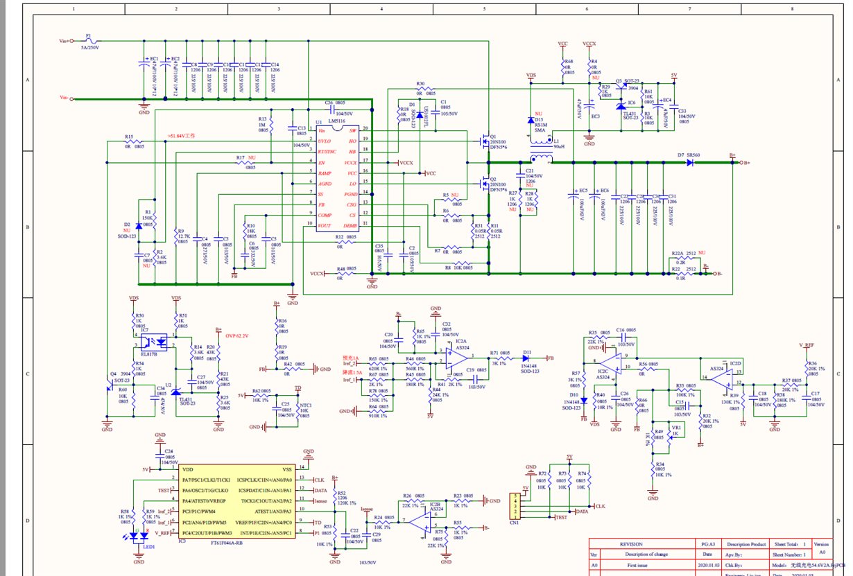
This post was asked for me by the Chinese engineer of TI。 I want to design a charger to charge the lithium battery. Using the connection method in the picture cannot achieve constant current, and the output of constant voltage is normal.The FB waveform and SW waveform when CV is loaded are shown in figure.I don't know what's wrong with the constant current
I have seen snva829.I want design the input 60-80VDC and output the constant voltage and current 55V/2A。So I can't use LM5117。And I want the exact constant voltage constant current, constant current point is changing.During charging, the battery voltage is 26V-39V constant current 0.5A and 39V-53V constant current 2A, which can be realized by changing the current reference.Finally, the constant voltage charge, so the simple constant current method does not work.My question is why the connection in the figure above works at constant voltage, but not at constant current.Is there any other method for LM5116 to achieve accurate constant voltage and constant current? Or do you have any other scheme to achieve it
Thanks for your reply. I have looked at Figure 1, but the regulator tube is used, and the constant voltage point is not correct. The final charging voltage requirement of lithium battery is very accurate, 54.6V±0.2V, so it is not feasible
The CV/CC transition point can be made more accurate by using a circuit more accurate than a Zener diode. Your existing scheme seems overly complicated to achieve this function. Why not eliminate the opto and CV circuit, then rely on the normal feedback loop for CV and just use an external CC control circuit to inject current into FB.
Yes, that's the basic idea -- use an amplifier to take the voltage across Rshunt and then inject an appropriate current into FB to reduce Vout in CC mode.
But this method won't work and will damage the chip.My understanding is that the steady-state FB voltage should be stable at 1.215V, which means that the output voltage is the voltage point you want to output at constant voltage, but it is lower than the constant voltage point at constant current, which is contradictory. Now I have found a way to realize constant voltage and constant current, as shown in the figure below. However, CC mode with load 2A cannot be started up, and the set overcurrent point is completely enough. It is ok to disconnect the constant current line.Don't know why? In addition, SW node oscillates when there is no load. It will be normal with load of more than 0.1A. Is it normal? No-load and light-load conditions are not described in the chip data sheet。Does it go into DCM and cause oscillations? In your 12V5A DEMO board, I have measured the no-load state without vibration. Or is my voltage loop parameter causing a no-load oscillation?
Looks like DCM is engaged. Go ahead and enable forced PWM (FPWM) for constant Fsw at light loads (see datasheet for more detail).
In terms of debug, it's always better to get the voltage loop operating correctly first, then add the CC loop. You can use the LM5116 quickstart calculator to check component values, particularly the voltage loop compensation parameters. Plese send the file for review if you need further assistance.
PS: pulling on COMP is not normally recommended as you're fighting against the internal voltage loop error amp.