This thread has been locked.

If you have a related question, please click the "Ask a related question" button in the top right corner. The newly created question will be automatically linked to this question.

BQ25790: BQ25790 Automatic recharge problem

Part Number: BQ25790

Hi Ti guys.

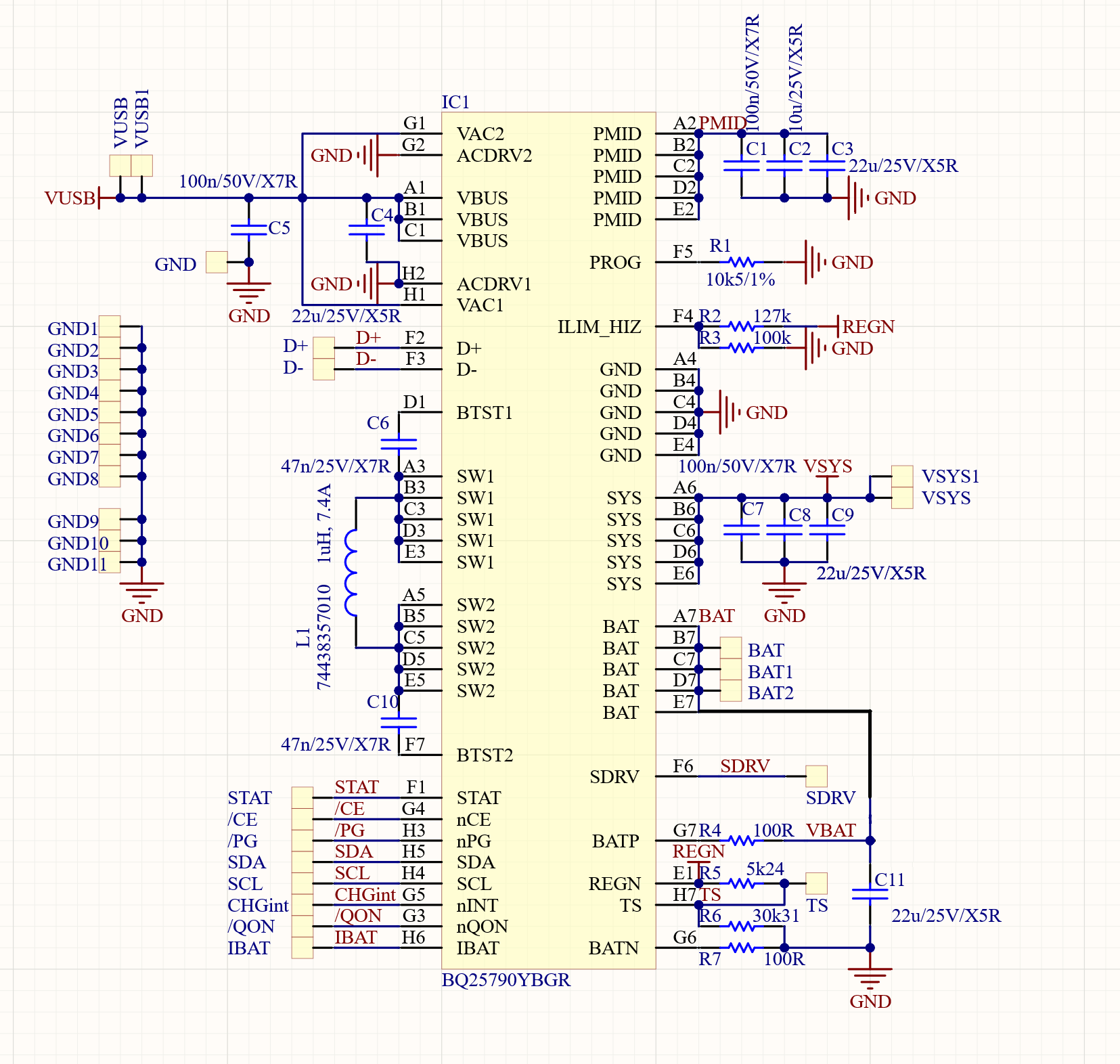
I've a custom development board with the BQ25790 on it. I want to use it to charge a 3-cell battery from the 5V source. For now it is connected in the VBUS only mode. It is also important that automatic recharge is working.

MY GOAL

So what I want is when VBUS is applied, charging should start and finish when VBAT is 12600mV. Then when VBAT falls bellow 11800mV the charging should restart automatically without any pin toggle or register read/write. Don't know it the termination is needed or if it is connected with the automatic recharge process (didn't find that info in the datasheet)...

BQ25790 is initialized at the boot in the "bq25790_init" function. Then its status is displayed every second inthe function "bq25790_monitor". When INT pin of the BQ25790 is pulled low the "bq25790_on_int_low" is called and then the flag registers (REG22 - REG27) are read in the "bq25790_process" function.

SO WHAT IS THE PROBLEM

At that point the battery voltage is around 12V and VBUS is applied, charging cycle started and status line from charger is:

VBAT: 11954mV, IBAT: 295mA, CHG STATUS: 3, BAT PRESENT: 1, S0: 0x89, S1: 0x63, S2: 0x01, S3: 0x00, S4: 0x00, F0: 0x00, F1: 0x00

So this looks normal, current flows in the battery and charging mode is "CC charging" (status 3 from the datasheet). Then when battery voltage increases, charging status changes to "CV charging" (status 4) and the IBAT current decreases. If the load is connected to the VSYS at this time, battery voltage drops and charging status changes back to "CC charging" and the IBAT register value increases, which is normal operation.

But then at a random time charger gets stuck at the status "CC charging" but the IBAT register values is 0, also there is no current coming in or out of the battery (SHIP FET isn't used here.), but battery voltage is around 12.2V which means it should be charging. Following are some line from the monitor function:


VBAT: 12332mV, IBAT: 277mA, CHG STATUS: 4, BAT PRESENT: 1, S0: 0x89, S1: 0x83, S2: 0x01, S3: 0x00, S4: 0x00, F0: 0x00, F1: 0x00
CHG_FLAG1: 0x80
VBAT: 12332mV, IBAT: 277mA, CHG STATUS: 3, BAT PRESENT: 1, S0: 0x89, S1: 0x63, S2: 0x01, S3: 0x00, S4: 0x00, F0: 0x00, F1: 0x00
CHG_FLAG1: 0x80
VBAT: 12459mV, IBAT: 278mA, CHG STATUS: 4, BAT PRESENT: 1, S0: 0x89, S1: 0x83, S2: 0x01, S3: 0x00, S4: 0x00, F0: 0x00, F1: 0x00
CHG_FLAG1: 0x80
VBAT: 12494mV, IBAT: 274mA, CHG STATUS: 3, BAT PRESENT: 1, S0: 0x89, S1: 0x83, S2: 0x01, S3: 0x00, S4: 0x00, F0: 0x00, F1: 0x00
CHG_FLAG1: 0x80

...
VBAT: 12547mV, IBAT: 215mA, CHG STATUS: 3, BAT PRESENT: 1, S0: 0x89, S1: 0x63, S2: 0x01, S3: 0x00, S4: 0x00, F0: 0x00, F1: 0x00
VBAT: 12190mV, IBAT: 107mA, CHG STATUS: 3, BAT PRESENT: 1, S0: 0x89, S1: 0x63, S2: 0x01, S3: 0x00, S4: 0x00, F0: 0x00, F1: 0x00
VBAT: 12001mV, IBAT: 53mA, CHG STATUS: 3, BAT PRESENT: 1, S0: 0x89, S1: 0x63, S2: 0x01, S3: 0x00, S4: 0x00, F0: 0x00, F1: 0x00
VBAT: 11865mV, IBAT: 26mA, CHG STATUS: 3, BAT PRESENT: 1, S0: 0x89, S1: 0x63, S2: 0x01, S3: 0x00, S4: 0x00, F0: 0x00, F1: 0x00
VBAT: 11865mV, IBAT: 13mA, CHG STATUS: 3, BAT PRESENT: 1, S0: 0x89, S1: 0x63, S2: 0x01, S3: 0x00, S4: 0x00, F0: 0x00, F1: 0x00
VBAT: 11783mV, IBAT: 13mA, CHG STATUS: 3, BAT PRESENT: 1, S0: 0x89, S1: 0x63, S2: 0x01, S3: 0x00, S4: 0x00, F0: 0x00, F1: 0x00
VBAT: 11756mV, IBAT: 6mA, CHG STATUS: 3, BAT PRESENT: 1, S0: 0x89, S1: 0x63, S2: 0x01, S3: 0x00, S4: 0x00, F0: 0x00, F1: 0x00
VBAT: 11747mV, IBAT: 3mA, CHG STATUS: 3, BAT PRESENT: 1, S0: 0x89, S1: 0x63, S2: 0x01, S3: 0x00, S4: 0x00, F0: 0x00, F1: 0x00
VBAT: 11715mV, IBAT: 1mA, CHG STATUS: 3, BAT PRESENT: 1, S0: 0x89, S1: 0x63, S2: 0x01, S3: 0x00, S4: 0x00, F0: 0x00, F1: 0x00
VBAT: 11696mV, IBAT: 0mA, CHG STATUS: 3, BAT PRESENT: 1, S0: 0x89, S1: 0x63, S2: 0x01, S3: 0x00, S4: 0x00, F0: 0x00, F1: 0x00


And then here it is stuck and it won't start automaticall recharge procedure. There are two ways to start new charging cycle:

1. To reconnect the VBUS power supply (5V).

2. To set EN_CHG bit 0 and then back to 1 but usually this must be done a few times to restart charging cycle.

So what am I doing wrong and what am I missing. Kindly asking you to help me out.

SIMPLIFIED FUNCTIONS

Following is the init procedure (simplified for better readability):

void bq25790_init(void){

set_bq25790_CE_pin(HIGH); // Disable charging

bq25790_termination_ctrl.reg_rst = 1; // Reset the BQ25790 and wait 250ms
HAL_Delay(250);

bq25790_read_all_registers(); // Read all registers - default values are same as the one from the datasheet...

bq25790_chg_ctrl1.wdt = 0; // Disable wdt
bq25790_chg_ctrl1.wdt_rst = 1; // Reset watchdog status
bq25790_prechg_ctrl.iprechg = 1; // Set the pre-charge current regulation limit to 40 mA.
bq25790_inp_v_lim.vinpm = 0x28; // Set the input voltage regulation limit (VINDPM) to 4000mV (open circuit voltage).
bq25790_chgr_i_lim.ichg = 0x1E; // To set max. constant-current (CC) charging regulation limit to 300mA.
bq25790_inp_i_lim.iindpm = 0x14A; // To set input current regulation limit to 3300mA.

// VSYSMIN is automatically set to 9000mV because of the hardware configuration, and a read of the register confirms that.

// VREG is is automatically set to 12600mV because of the hardware configuration, and a read of the register confirms that.

bq25790_rechg_ctrl.trechg = 3; // Battery recharge deglich time 2048ms
bq25790_rechg_ctrl.vrechg = 0x0F; // Automatic recharge at 11800mV -> (800mV - 50mV) / 50mV = 0x0F

bq25790_adc_ctrl.adc_avg = 1; // Running average
bq25790_adc_ctrl.adc_en = 1; // Enable ADC converter
bq25790_adc_ctrl.adc_rate = 0; // 15-bit effective resolution

bq25790_ntc_ctrl1.ts_ignore = 1; // Ignor temperature sensor - Not populated on the PCB

// Now when registers are set, enable charging

set_bq25790_CE_pin(LOW);
bq25790_chg_ctrl0.en_chg = 1;

}

Then a function for monitoring is called every second and when the INT pin goes low (simplified for better readability):

void bq25790_monitor(){ // Called every second and when the INT pin goes low...

bq25790_read_registers_from_tick(); // Here read all the necessary registers

PRINTF( "VBAT: %dmV, "
            "IBAT: %dmA, "
            "CHG STATUS: %d, "
            "BAT PRESENT: %d, "
            "S0: 0x%02X, "
            "S1: 0x%02X, "
            "S2: 0x%02X, "
            "S3: 0x%02X, "
            "S4: 0x%02X, "
            "F0: 0x%02X, "
            "F1: 0x%02X\n",
            bq25790_vbat_adc.vbat_adc,
            bq25790_ibat_adc.ibat_adc,
            bq25790_chg_status1.chg_stat,
            bq25790_chg_status2.vbat_present_stat,
            *(uint8_t*)&bq25790_chg_status0,
            *(uint8_t*)&bq25790_chg_status1,
            *(uint8_t*)&bq25790_chg_status2,
            *(uint8_t*)&bq25790_chg_status3,
            *(uint8_t*)&bq25790_chg_status4,
            *(uint8_t*)&bq25790_fault_status0,
            *(uint8_t*)&bq25790_fault_status1
);

}

Then there is also the interrupt callback and interrupt callback handling function (simplified for better readability):

void bq25790_on_int_low(void){ // Function must return fast (ISR function)

// This function is called every time when "INT" pin of the BQ25790 is pulled low.

handle_bq25790_interrupt++; (defined as global int)

}

void bq25790_process(void){ // Function can take time (called from main every 1ms)

if(handle_bq25790_interrupt){

handle_bq25790_interrupt--;

bq25790_read_flag_registers(); // Read all flag registers

if (*(uint8_t*)&bq25790_chg_flag0 > 0) PRINTF("CHG_FLAG0: 0x%02X\n", *(uint8_t*)&bq25790_chg_flag0);     
if (*(uint8_t*)&bq25790_chg_flag1 > 0)  PRINTF("CHG_FLAG1: 0x%02X\n", *(uint8_t*)&bq25790_chg_flag1);
if (*(uint8_t*)&bq25790_chg_flag2 > 0)  PRINTF("CHG_FLAG2: 0x%02X\n", *(uint8_t*)&bq25790_chg_flag2);
if (*(uint8_t*)&bq25790_chg_flag3 > 0)  PRINTF("CHG_FLAG3: 0x%02X\n", *(uint8_t*)&bq25790_chg_flag3);
if (*(uint8_t*)&bq25790_fault_flag0 > 0) PRINTF("FAULT_FLAG0: 0x%02X\n", *(uint8_t*)&bq25790_fault_flag0);
if (*(uint8_t*)&bq25790_fault_flag1 > 0) PRINTF("FAULT_FLAG1: 0x%02X\n", *(uint8_t*)&bq25790_fault_flag1); 

bq25790_monitor();    

}

}

Best regards,
Aleš Zupanc, firmware developer
PoLabs d.o.o. 1000 Ljubljana, Slovenia

  • Hi Ales,

    Based on your status and fault registers, the charger appears to be running in DPM/supplement mode which means that the input power supply is not strong enough to both power the load at SYS and provide the total charge current.  When in DPM, the charger does not terminate and so cannot recharge.  I have some questions:

    What is your load on SYS?  Is the voltage at BAT pin greater than or less at SYS pin?  If V(BAT) > V(SYS) then the charger is in supplement mode. 

    Is your IBAT measurement using the charger's ADC?  If so, are you accounting for the two's complement which will report negative current if there is no VBUS or if in deep supplement mode?

    At the moment, I can't explain why power cycling the charger results it in starting to charge again. 

    Regards,

    Jeff

  • Hi Jeff.

    I see... Somehow the chg_status0 register wasn't updating during the time when screenshot was taken... I fixed this and now the chg_status0 is 0x09 and not 0x89 as before. Also I cheched the VSYS voltage and it'is the same as VBAT.

    The current measurement that is used are the 2 bytes read from the bq25790_ibat_adc register (0x33). So the 0x33 and 0x34 registers and then stored in 16-bit unsigned integer. So a ray value from the BQ's register is displayed...

    The problem occurs even if SYS is totally unloaded. So charger is in the CV-charging state, some current flows in the battery and then at some point status changes to CC-charging state and no curent flows in the battery (checked with the A-meter in series with the battery)... Then even when voltage falls, charging doesn't start automatically... Then again if the bq25790_chg_ctrl4.force_vindpm_det bit is set, charging is started again...

    Here is a device boot procedure. First it resets the BQ25790, then read back all the registers, set the desired values as described in the first post and then it starts charging for couple of seconds. After that the charging is stopped by the BQ25790 and a button is pressed and the bq25790_chg_ctrl4.force_vindpm_det bit is set and charging restarts again...

    [BOOT]

    0x00 -> 0x1A
    0x01 -> 0x04EC
    0x03 -> 0x0064
    0x05 -> 0x2B
    0x06 -> 0x00AC
    0x08 -> 0xC3
    0x09 -> 0x05
    0x0A -> 0xA3
    0x0B -> 0x00DC
    0x0D -> 0x4B
    0x0E -> 0x3D
    0x0F -> 0xA2
    0x10 -> 0xB5
    0x11 -> 0x40
    0x12 -> 0x00
    0x13 -> 0x01
    0x14 -> 0x16
    0x15 -> 0xAA
    0x16 -> 0xC0
    0x17 -> 0x7A
    0x18 -> 0x54
    0x19 -> 0x00AC
    0x1B -> 0x09
    0x1C -> 0x03
    0x1D -> 0x01
    0x1E -> 0x00
    0x1F -> 0x04
    0x20 -> 0x00
    0x21 -> 0x00
    0x22 -> 0x00
    0x23 -> 0x00
    0x24 -> 0x00
    0x25 -> 0x04
    0x26 -> 0x00
    0x27 -> 0x00
    0x28 -> 0x00
    0x29 -> 0x00
    0x2A -> 0x00
    0x2B -> 0x00
    0x2C -> 0x00
    0x2D -> 0x00
    0x2E -> 0x30
    0x2F -> 0x00
    0x30 -> 0x00
    0x31 -> 0x0001
    0x33 -> 0x0000
    0x35 -> 0x13A8
    0x37 -> 0x0000
    0x39 -> 0x0000
    0x3B -> 0x2F02
    0x3D -> 0x31B8
    0x3F -> 0x035C
    0x41 -> 0x0039
    0x43 -> 0x0000
    0x45 -> 0x0000
    0x47 -> 0x00
    0x48 -> 0x01
    BUS CONNECTED!
    CHARGING_ENABLED
    BAT CONNECTED!
    CHG_FLAG3: 0x04
    VBAT: 12540mV, IBAT: 179mA, CHG STATUS: 0, BAT PRESENT: 1, S0: 0x09, S1: 0x03, S2: 0x01, S3: 0x00, S4: 0x00, F0: 0x00, F1: 0x00, viindpm: 4000, iindpm: 3300
    CHG_FLAG0: 0x80
    CHG_FLAG1: 0x80
    VBAT: 12624mV, IBAT: 143mA, CHG STATUS: 4, BAT PRESENT: 1, S0: 0x89, S1: 0x83, S2: 0x01, S3: 0x00, S4: 0x00, F0: 0x00, F1: 0x00, viindpm: 4000, iindpm: 3300
    VBAT: 12598mV, IBAT: 127mA, CHG STATUS: 4, BAT PRESENT: 1, S0: 0x89, S1: 0x83, S2: 0x01, S3: 0x00, S4: 0x00, F0: 0x00, F1: 0x00, viindpm: 4000, iindpm: 3300
    VBAT: 12576mV, IBAT: 122mA, CHG STATUS: 4, BAT PRESENT: 1, S0: 0x89, S1: 0x83, S2: 0x01, S3: 0x00, S4: 0x00, F0: 0x00, F1: 0x00, viindpm: 4000, iindpm: 3300
    VBAT: 12534mV, IBAT: 114mA, CHG STATUS: 4, BAT PRESENT: 1, S0: 0x89, S1: 0x83, S2: 0x01, S3: 0x00, S4: 0x00, F0: 0x00, F1: 0x00, viindpm: 4000, iindpm: 3300
    VBAT: 12592mV, IBAT: 195mA, CHG STATUS: 4, BAT PRESENT: 1, S0: 0x89, S1: 0x83, S2: 0x01, S3: 0x00, S4: 0x00, F0: 0x00, F1: 0x00, viindpm: 4000, iindpm: 3300
    VBAT: 12564mV, IBAT: 113mA, CHG STATUS: 4, BAT PRESENT: 1, S0: 0x89, S1: 0x83, S2: 0x01, S3: 0x00, S4: 0x00, F0: 0x00, F1: 0x00, viindpm: 4000, iindpm: 3300
    VBAT: 12618mV, IBAT:  89mA, CHG STATUS: 4, BAT PRESENT: 1, S0: 0x09, S1: 0x83, S2: 0x01, S3: 0x00, S4: 0x00, F0: 0x00, F1: 0x00, viindpm: 4300, iindpm: 2560
    VBAT: 12598mV, IBAT:  96mA, CHG STATUS: 4, BAT PRESENT: 1, S0: 0x09, S1: 0x83, S2: 0x01, S3: 0x00, S4: 0x00, F0: 0x00, F1: 0x00, viindpm: 4300, iindpm: 2560
    VBAT: 12678mV, IBAT: 116mA, CHG STATUS: 4, BAT PRESENT: 1, S0: 0x09, S1: 0x83, S2: 0x01, S3: 0x00, S4: 0x00, F0: 0x00, F1: 0x00, viindpm: 4300, iindpm: 2560
    VBAT: 12646mV, IBAT: 105mA, CHG STATUS: 4, BAT PRESENT: 1, S0: 0x09, S1: 0x83, S2: 0x01, S3: 0x00, S4: 0x00, F0: 0x00, F1: 0x00, viindpm: 4300, iindpm: 2560
    VBAT: 12636mV, IBAT:  95mA, CHG STATUS: 4, BAT PRESENT: 1, S0: 0x09, S1: 0x83, S2: 0x01, S3: 0x00, S4: 0x00, F0: 0x00, F1: 0x00, viindpm: 4300, iindpm: 2560
    VBAT: 12580mV, IBAT:  91mA, CHG STATUS: 4, BAT PRESENT: 1, S0: 0x09, S1: 0x83, S2: 0x01, S3: 0x00, S4: 0x00, F0: 0x00, F1: 0x00, viindpm: 4300, iindpm: 2560
    CHG_FLAG1: 0x80

    | STOPPED CHARGING HERE |
    VBAT: 12220mV, IBAT:   0mA, CHG STATUS: 3, BAT PRESENT: 1, S0: 0x09, S1: 0x63, S2: 0x01, S3: 0x00, S4: 0x00, F0: 0x00, F1: 0x00, viindpm: 4300, iindpm: 2560
    VBAT: 12190mV, IBAT:   0mA, CHG STATUS: 3, BAT PRESENT: 1, S0: 0x09, S1: 0x63, S2: 0x01, S3: 0x00, S4: 0x00, F0: 0x00, F1: 0x00, viindpm: 4300, iindpm: 2560
    VBAT: 12152mV, IBAT:   0mA, CHG STATUS: 3, BAT PRESENT: 1, S0: 0x09, S1: 0x63, S2: 0x01, S3: 0x00, S4: 0x00, F0: 0x00, F1: 0x00, viindpm: 4300, iindpm: 2560
    VBAT: 12114mV, IBAT:   0mA, CHG STATUS: 3, BAT PRESENT: 1, S0: 0x09, S1: 0x63, S2: 0x01, S3: 0x00, S4: 0x00, F0: 0x00, F1: 0x00, viindpm: 4300, iindpm: 2560


    ----------------- BUTTON PRESSED -----------------


    CHG_FLAG0: 0x80
    VBAT: 12516mV, IBAT: 108mA, CHG STATUS: 0, BAT PRESENT: 1, S0: 0x89, S1: 0x03, S2: 0x01, S3: 0x00, S4: 0x00, F0: 0x00, F1: 0x00, viindpm: 4300, iindpm: 2560
    CHG_FLAG1: 0x80
    VBAT: 12576mV, IBAT: 114mA, CHG STATUS: 4, BAT PRESENT: 1, S0: 0x89, S1: 0x83, S2: 0x01, S3: 0x00, S4: 0x00, F0: 0x00, F1: 0x00, viindpm: 4300, iindpm: 2560
    VBAT: 12602mV, IBAT: 216mA, CHG STATUS: 4, BAT PRESENT: 1, S0: 0x89, S1: 0x83, S2: 0x01, S3: 0x00, S4: 0x00, F0: 0x00, F1: 0x00, viindpm: 4300, iindpm: 2560
    VBAT: 12606mV, IBAT:  88mA, CHG STATUS: 4, BAT PRESENT: 1, S0: 0x09, S1: 0x83, S2: 0x01, S3: 0x00, S4: 0x00, F0: 0x00, F1: 0x00, viindpm: 4300, iindpm: 2560
    VBAT: 12552mV, IBAT:  83mA, CHG STATUS: 4, BAT PRESENT: 1, S0: 0x09, S1: 0x83, S2: 0x01, S3: 0x00, S4: 0x00, F0: 0x00, F1: 0x00, viindpm: 4300, iindpm: 2560
    VBAT: 12566mV, IBAT:  73mA, CHG STATUS: 4, BAT PRESENT: 1, S0: 0x09, S1: 0x83, S2: 0x01, S3: 0x00, S4: 0x00, F0: 0x00, F1: 0x00, viindpm: 4300, iindpm: 2560
    CHG_FLAG1: 0x80

    | STOPPED CHARGING HERE AGAIN |
    VBAT: 12300mV, IBAT:   0mA, CHG STATUS: 3, BAT PRESENT: 1, S0: 0x09, S1: 0x63, S2: 0x01, S3: 0x00, S4: 0x00, F0: 0x00, F1: 0x00, viindpm: 4300, iindpm: 2560
    VBAT: 12236mV, IBAT:   0mA, CHG STATUS: 3, BAT PRESENT: 1, S0: 0x09, S1: 0x63, S2: 0x01, S3: 0x00, S4: 0x00, F0: 0x00, F1: 0x00, viindpm: 4300, iindpm: 2560
    VBAT: 12146mV, IBAT:   0mA, CHG STATUS: 3, BAT PRESENT: 1, S0: 0x09, S1: 0x63, S2: 0x01, S3: 0x00, S4: 0x00, F0: 0x00, F1: 0x00, viindpm: 4300, iindpm: 2560
    VBAT: 12158mV, IBAT:   0mA, CHG STATUS: 3, BAT PRESENT: 1, S0: 0x09, S1: 0x63, S2: 0x01, S3: 0x00, S4: 0x00, F0: 0x00, F1: 0x00, viindpm: 4300, iindpm: 2560
    VBAT: 12114mV, IBAT:   0mA, CHG STATUS: 3, BAT PRESENT: 1, S0: 0x09, S1: 0x63, S2: 0x01, S3: 0x00, S4: 0x00, F0: 0x00, F1: 0x00, viindpm: 4300, iindpm: 2560


    Looking at the STAT pin everything looks normal, its state is LOW and not changing (it is enabled and it goes high when I manually disable the charging, etc). Also the PG pin is LOW so I assume that power supply is OK.

    Best regards,
    Aleš Zupanc, firmware developer
    PoLabs d.o.o. 1000 Ljubljana, Slovenia

  • Hi Ales,

    The IBAT ADC register will only read current going into the battery with your configuration.  You will need to update your code to accommodate two's complement in you want it to read negative (supplement or OTG mode) current.  Your ADC Die temp likely has the same issue.

    You boot register show that the charger is in TS Cool, which lowers the charge current to 20% of the ICHG register setting.  How is TS pin connected?  Can you send your schematic?

    You mention a current meter (ammeter).  Is it in series between the charger IC and battery (or simulated battery)?  If so, please short it out and try again.  The ammeter, especially when in auto range mode, causes problems for the charger.  

    Can you send all of the status and fault registers after charge stops?  Please ensure that the host performs only one I2C read of the fault registers after charge stops, otherwise, the faults will clear.

    Regards,

    Jeff

  • Hi Ales,

    BTW, registers I need are 0x1B to 0x27.

    Thanks.
    Jeff

  • Hi Jeff,

    So to modify the ADC reading I've implemented the following function, but I'm not sure if it's correct. If I understood you right, there should be a negative current reading when the current is going out of the battery (when in battery only mode)..? But even with this function I'm getting only -1mA to about -5mA reading but only from time to time other time I'm only getting 0mA during the negative current from battery.

    A function to convert value of twos complement in to signed integer (16-bit adc measurement, effective only 15 bits):

    int16_t twos_complement(uint32_t val){
        uint16_t mask = 1<<15;
        return -(val & mask) + (val & ~mask);
    }

    All registers when charger stops the charging and gets stuck

    VBAT: 12536mV, IBAT: 324mA, CHG STATUS: 3, BAT PRESENT: 1, S0: 0x89, S1: 0x63, S2: 0x01, S3: 0x00, S4: 0x00, F0: 0x00, F1: 0x00, viindpm: 4000, iindpm: 3300
    VBAT: 12544mV, IBAT: 263mA, CHG STATUS: 3, BAT PRESENT: 1, S0: 0x89, S1: 0x63, S2: 0x01, S3: 0x00, S4: 0x00, F0: 0x00, F1: 0x00, viindpm: 4000, iindpm: 3300
    CHG_FLAG1: 0x80
    VBAT: 12542mV, IBAT: 274mA, CHG STATUS: 3, BAT PRESENT: 1, S0: 0x89, S1: 0x63, S2: 0x01, S3: 0x00, S4: 0x00, F0: 0x00, F1: 0x00, viindpm: 4000, iindpm: 3300
    CHG_FLAG1: 0x80
    VBAT: 12028mV, IBAT:   0mA, CHG STATUS: 3, BAT PRESENT: 1, S0: 0x09, S1: 0x63, S2: 0x01, S3: 0x00, S4: 0x00, F0: 0x00, F1: 0x00, viindpm: 4300, iindpm: 2560
    VBAT: 11990mV, IBAT:   0mA, CHG STATUS: 3, BAT PRESENT: 1, S0: 0x09, S1: 0x63, S2: 0x01, S3: 0x00, S4: 0x00, F0: 0x00, F1: 0x00, viindpm: 4300, iindpm: 2560

    ...

    CHG_FLAG1: 0x80
    VBAT: 12584mV, IBAT: 276mA, CHG STATUS: 4, BAT PRESENT: 1, S0: 0x09, S1: 0x83, S2: 0x01, S3: 0x00, S4: 0x00, F0: 0x00, F1: 0x00, viindpm: 4300, iindpm: 2560
    VBAT: 12634mV, IBAT: 284mA, CHG STATUS: 4, BAT PRESENT: 1, S0: 0x09, S1: 0x83, S2: 0x01, S3: 0x00, S4: 0x00, F0: 0x00, F1: 0x00, viindpm: 4300, iindpm: 2560

    ...

    CHG_FLAG1: 0x80
    VBAT: 11834mV, IBAT:   0mA, CHG STATUS: 3, BAT PRESENT: 1, S0: 0x09, S1: 0x63, S2: 0x01, S3: 0x00, S4: 0x00, F0: 0x00, F1: 0x00, viindpm: 4300, iindpm: 2560

    ----------------- BUTTON PRESSED (read all registers) -----------------
    0x00 -> 0x1A
    0x01 -> 0x04EC
    0x03 -> 0x001E
    0x05 -> 0x2B
    0x06 -> 0x0092
    0x08 -> 0xC1
    0x09 -> 0x05
    0x0A -> 0x81
    0x0B -> 0x00DC
    0x0D -> 0x4B
    0x0E -> 0x3D
    0x0F -> 0xA0
    0x10 -> 0xB0
    0x11 -> 0x40
    0x12 -> 0x00
    0x13 -> 0x01
    0x14 -> 0x16
    0x15 -> 0xAA
    0x16 -> 0xC0
    0x17 -> 0x7A
    0x18 -> 0x55
    0x19 -> 0x0092
    0x1B -> 0x09
    0x1C -> 0x63
    0x1D -> 0x01
    0x1E -> 0x00
    0x1F -> 0x00
    0x20 -> 0x00
    0x21 -> 0x00
    0x22 -> 0x00
    0x23 -> 0x00
    0x24 -> 0x00
    0x25 -> 0x00
    0x26 -> 0x00
    0x27 -> 0x00
    0x28 -> 0x00
    0x29 -> 0x00
    0x2A -> 0x00
    0x2B -> 0x00
    0x2C -> 0x00
    0x2D -> 0x00
    0x2E -> 0xB0
    0x2F -> 0x00
    0x30 -> 0x00
    0x31 -> 0x0000
    0x33 -> 0x0000
    0x35 -> 0x13A8
    0x37 -> 0x0014
    0x39 -> 0x0000
    0x3B -> 0x2E40
    0x3D -> 0x2E82
    0x3F -> 0x035F
    0x41 -> 0x0026
    0x43 -> 0x0D90
    0x45 -> 0x0D90
    0x47 -> 0x00
    0x48 -> 0x01

    About the TS cool status during the boot time... During the boot sequence (after the read of all the registers) the TS_IGNORE but is set. Currently I'd like to ignore all temperature settings since the temperature sensor isn't mounted on the testing PCB yet.

    Schematic

    image.png

    Best regards,
    Aleš Zupanc, firmware developer
    PoLabs d.o.o. 1000 Ljubljana, Slovenia

  • Hi Ales,

    Unfortunately, your schematic did not come through.  Can you repost?

    Regarding the two's complement code, I am hardware person, not software.  I will forward to someone else and ask them to review.

    Regarding your reads, you are not reading all of the Status and Fault registers. If charging has stopped, there should be a fault generated when it stops. They run from REG0x1B to REG0x27.  If you cannot read those, then I will need oscilloscope plots of the waveforms, SYS, BAT, VBUS, SW.

    Regards,
    Jeff

  • Reposting the schematic again here.

    Okay yes that is true, the registers that I've sent before weren't read right after the charging stopped, but when I pressed the button... My bad, sorry.

    So now I've changed the code, so that all registers are read right after IBAT == 0 and charging status is still 3 (CC-charging)... This are the values:

    VBAT: 12606mV, IBAT: 291mA, CHG STATUS: 3, BAT PRESENT: 1, S0: 0x09, S1: 0x63, S2: 0x01, S3: 0x00, S4: 0x00, F0: 0x00, F1: 0x00, viindpm: 4200, iindpm: 0
    CHG_FLAG1: 0x80
    VBAT: 12416mV, IBAT: 0mA, CHG STATUS: 3, BAT PRESENT: 1, S0: 0x09, S1: 0x63, S2: 0x01, S3: 0x00, S4: 0x00, F0: 0x00, F1: 0x00, viindpm: 4200, iindpm: 0
    CHG_FLAG1: 0x80
    0x00 -> 0x1A
    0x01 -> 0x04EC
    0x03 -> 0x001E
    0x05 -> 0x2A
    0x06 -> 0x0032
    0x08 -> 0xC1
    0x09 -> 0x05
    0x0A -> 0x81
    0x0B -> 0x00DC
    0x0D -> 0x4B
    0x0E -> 0x3D
    0x0F -> 0xA0
    0x10 -> 0xB0
    0x11 -> 0x40
    0x12 -> 0x00
    0x13 -> 0x01
    0x14 -> 0x16
    0x15 -> 0xAA
    0x16 -> 0xC0
    0x17 -> 0x7A
    0x18 -> 0x55
    0x19 -> 0x0032
    0x1B -> 0x09
    0x1C -> 0x63
    0x1D -> 0x01
    0x1E -> 0x00
    0x1F -> 0x00
    0x20 -> 0x00
    0x21 -> 0x00
    0x22 -> 0x00
    0x23 -> 0x00
    0x24 -> 0x00
    0x25 -> 0x00
    0x26 -> 0x00
    0x27 -> 0x00
    0x28 -> 0x00
    0x29 -> 0x00
    0x2A -> 0x00
    0x2B -> 0x00
    0x2C -> 0x00
    0x2D -> 0x00
    0x2E -> 0xB0
    0x2F -> 0x00
    0x30 -> 0x00
    0x31 -> 0x0000
    0x33 -> 0x0000
    0x35 -> 0x13A8
    0x37 -> 0x000C
    0x39 -> 0x0000
    0x3B -> 0x2E9C
    0x3D -> 0x2EF0
    0x3F -> 0x035D
    0x41 -> 0x0056
    0x43 -> 0x0D65
    0x45 -> 0x0D65
    0x47 -> 0x00
    0x48 -> 0x01

    One funny thing that I noticed is that IINDPM becomes 0... I will also provide you the oscilloscope plots, but probably not today, but tomorrow...

    Regards, Ales Zupanc.

  • Hi Ales,

    I do not see an obvious error with the schematic.

    Unfortunately, the data you provided is not showing a fault.  So, I will need to see the waveforms and go from there.  I don't know why iindpm would set itself to 0.  I am not aware of a fault or event that would do that.  Registers 0x06 and 0x19 are reporting IINDPM=500mA.  Where are you reading iindpm?

    By the way, my software guy thinks your two's complement code will work.

    Regards,

    Jeff

  • HI Jeff.

    I also think thant it's best that I provide you the waveforms and then we work on...

    Sometimes when I read the IINDPM after the charging is stopped, it reads 0 and sometimes 500mA... Don't know why that is. I see that IINDPM in read one time before the read_all_registers() is called (it is read every second during the monitoring, so maybe that's the problem when it is read every second?).

    The two's complement code does work, I can see the minus sign and so on but when load is connected to the SYS I can't see the negative current from the battery... But I think that's not the case for here...

    I'll provide you the waveforms in a few days.

    Regards, Aleš Zupanc.

  • Hi Jeff.

    So I'm coming back to you now with a few oscilloscope plots.

    So the problem I'm having right now is straight forward. Battery is being charged until 12.6V. Then Charging status changes from 4 (CV-charging) back to 3 (CC-charging) but actually there is no current flow in the battery (refer to plot images)... Then when some load is applied to the SYS, the battery voltage drops and I'd expect that automatic recharging would start without any action over the I2C bu but id doesn't start! 

    1. According the datasheet, if I'm not mistaken, charging should restart automatically since no error were detected. Is that right?

    I hope that you are able to read out something useful from the plots (attached as .pdf file)

    auto_recharge_not_working.pdf

    Regards,

    Ales Zupanc

  • Hi Ales,

    After the battery voltage sensed at BATP hits VBATREG (i.e. battery charge terminated), the BATP voltage needs to fall below the recharge threshold voltage (VREG set in VRECHG_3:0, default=200mV).  I can't tell from your scope plots what the battery is.

    Also, the SW node measurement must be from the wrong SW pin.  There are 2.  SW1 has pulsing waveform when the converter is bucking (VBUS>VSYS) and SW2 has pulsing waveform when the converter is boosting (VBUS<VSYS).  I assume that you system load is getting its power so the converter is switching?

    Regards,

    Jeff

  • Hi Jeff,

    sorry for the slow response... BATP Voltage is bellow the recharge threshold voltage. The battery can get totally discharged so that the voltage falls bellow the 9.5V but the recharging would still not start. The battery voltage on the scope plots is almost completely the same as VSYS...

    I've measured the SW1 pin, should it be SW2?

    I still don't know what is the problem that the recharging doesn't start automatically...

    Regards, Ales Zupanc

  • Hi Alex,

    Yes, you should see switching on SW1 or SW2.

    Regarding why there is not recharge, the only reason I can think of for no recharge is safety timer timeout or TS fault, neither of which your registers are showing.  If the SYS voltage is being regulated to provide power to the load, the buck converter is connected correctly.  If you replace the battery with a simulated battery like a Keithley sourcemeter or 4-quadrant power supply, does it charge correctly?

    Regards,

    Jeff