This thread has been locked.

If you have a related question, please click the "Ask a related question" button in the top right corner. The newly created question will be automatically linked to this question.

BQ24133: Want to add a boost converter from battery to the output

Part Number: BQ24133

Instead of having a 3 cell battery, I wanted to use a single cell li-pol 3.7V battery to power a device that needs 12V. I tried to do this:

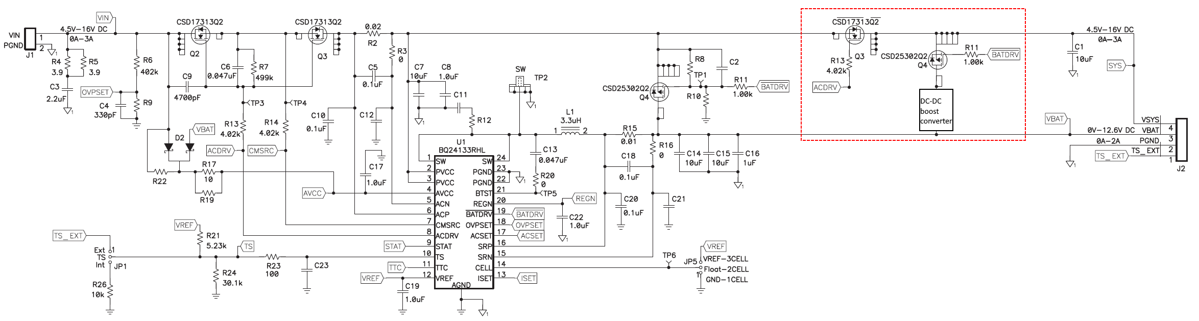
In the red box are my changes. The boost converter will boost up to 12V. Will this work?

  • Forgot to add: the input is 12V.

  • Aslan,

    I am a bit confused. Why are the two additional FETs necessary if the body diode of can be used to pass power to SYS in the absence of BATDRV and VIN. Why not just connect the boost converter to SYS?

    Thanks,

    Ricardo

  • Ricardo,

    The first N-MOS is needed to isolate the sys from PVCC node, when Vin is not connected. There is a comparator inside the BQ that compares Vpvcc and Vsrn(Vbat). I am assuming that if Vpvcc > Vbat, then BQ thinks that Vin is connected. 

    I put the second P-MOS at the output of the boost converter just so that the converter wouldn't output any current when Vin is present. 


  • Aslan,

    Oh I see. The basic operation is that when the adapter is not present you want the boost converter to pass 12V to SYS by boosting from the battery. When the adapter is present, you want to disconnect the output of the boost converter.

    The theory here works, but the circuit is wrong. You will need to flip the orientation of the PFET.

    The body diodes of the PFET will allow power to flow from the output of the boost converter even when the adapter is present.

    I hope this resolves your issue,

    Ricardo

  • Ricardo,

    I am not sure how the body diode will conduct current if  Vsys => VboostOut. 

    I tried assembling the circuit above and almost everything works great: 

    Vin = True, bat != connected -> everything works as expected.

    Vin = False, bat = connected -> everything works as expected: Vsys = 12V(from boost converter).

    Vin = True, bat = connected -> BQ charges the battery and boost converter does not output current.

    Vin = True, bat = connected, but Vin disconnected (to see if BQ switched to battery operation) -> does not work correctly:

    LED still flashing, ACDRV is boosting CMSRS and due to that the first N-MOS is open and letting 12V go into PVCC. The BATDRV is high, closing the P-MOS, but due to the body diode, current flows through. I feel like reversing the direction of the P-MOS is not the best decision.  

     I feel like there is a timing issue here.

  • Aslan,

    I understand now.

    As for your issue, what voltages are you observing under this condition?

    Vin = True, bat = connected, but Vin disconnected (to see if BQ switched to battery operation) -> does not work correctly

    Best Regards,

    Ricardo

  • Ricardo,

    Sorry for not replying sooner. My company is on lockdown due to the virus and the office is closed. I can't measure anything right now. I will post the voltages after I get back to the office. 

    Aslan