This thread has been locked.

If you have a related question, please click the "Ask a related question" button in the top right corner. The newly created question will be automatically linked to this question.

BQ24070: Not switching to battery power when supply is removed

Part Number: BQ24070

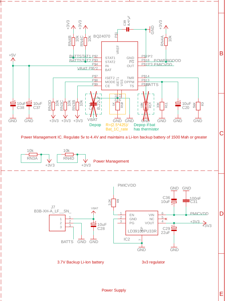
We have integrated the BQ24070 in our design following the datasheet according to the application note of section 9.2, and using the reference layout of section 11.2.

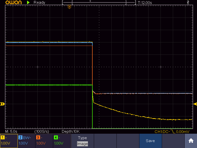
Although our board powers on, charges our Li-ion batteries and reports charging state as expected, our board does not switch over to the Li-ion battery when power is removed, even when the Li-ion is fully charged.

We have spent quite some time trying to understand the problem with our design, but have been unsuccessful.

Attached is the power management subsystem of our schematic. Note that since our batteries do no have thermistors, we have populated R14. 

Help would be greatly appreciated!

_

  • Hi Michael,

    Thanks for the information. Looking at the schematic, I do have a few questions. Would you be able to answer the following:

    • Was there a voltage at the OUT pin when the device when a voltage is applied at the IN?
    • Can you provide a voltage and current waveform of the following when removing power at the IN pin?
      • IN pin
      • OUT pin
      • BAT pin
      • TS pin


  • Hello Anthony, 

    We have tried to get as much of this info as possible, however it is not possible to instrument our pcb for current management.

    We think that something very strange is going on and hope that the voltage traces we have recorded may be enough to provide good insight.

    Q1:Was there a voltage at the OUT pin when the device when a voltage is applied at the IN? :Yes, 5.06V.

    Q2: Can you provide a voltage and current waveform of the following when removing power at the IN pin, OUT pin, BAT pi, TS pin?:We have only been able to capture Voltage waveforms. We have attached waveforms for the power off transition in two formats, csv and .bmp

    Measuring these waveforms was quite concerning to us, we found that of the pins you mentioned were outside of the absolute maximum ratings in table 7.1. Could you please verify our schematic? We are not sure why this would be.

    The values of these pins can be summarized as follows

    POWER ON:

    IN 5.01V

    OUT 5.01V

    BAT 4.95V

    TS 1.75V

    Battery 4.185V

    POWER OFF:

    IN -1.41V

    OUT 0.8V

    BAT 0.8V

    TS -2.05V

    Battery 4.185V

    Browsing the datasheet, we see that

    Mappings in the .csv file and .bmp

    Ch1 (Yellow) = IN, Ch2 (Blue) = OUT, Ch3 (Red) = BAT, Ch4 (Green) = Ts

    Waveform

    20201114_125032bm.csv

  • Hi Anthony.

    Besides gathering our voltage waveforms we also tried changing our C20 to 10nF, but the board still does not switch over to battery power.

  • Hi Michael,

    Yes the negative voltages seen on the IN and TS pin look like a standout issue. Few questions:

    Does this occur if you were to disable the 3V3 regulator by pulling the EN pin low?

    Is there also a board layout that can be provided?

    Were there any tests conducted prior to seeing this issue?

    What is being used to power the IN pin (is it a power supply?) and what is the 3V3 power regulator going to provide power to?

    The concern is that since there are voltages seen outside of the absolute maximum ratings, there may be permanent damages. 

  • Hi Michael,

    I haven't seen any updates. Are there any changes/updates here?

  • Hi Anthony,

    I've not been able to get to the lab to make the measurements you asked for. Please bear with me, it is currently quite difficult to do any kind of testing.

    It would help if you could weigh in on the value of C20. Would 10nF be a better choice of value? We were also seeing intermittent problems with battery-less power on. Would 33uF for C28 possibly help here?

    As for the performance of our board, hopefully I'll be able to check in the coming couple of weeks.

    Michael

  • Hi Michael,

    Thanks for the quick update! It might be helpful for you to know that threads will automatically lock themselves after a month of no activity. Hopefully we can get an update just so that you don't have to create a new thread.

    Do you have multiple units you can test this on? If you're worried about sending your board layout on a public forum, you can also send these files to me through email if you wish. My email is a-pham@ti.com.