This thread has been locked.

If you have a related question, please click the "Ask a related question" button in the top right corner. The newly created question will be automatically linked to this question.

TPS54560B: TPS54560BDDAR: Possible load transient issue

Part Number: TPS54560B

Hi Team,

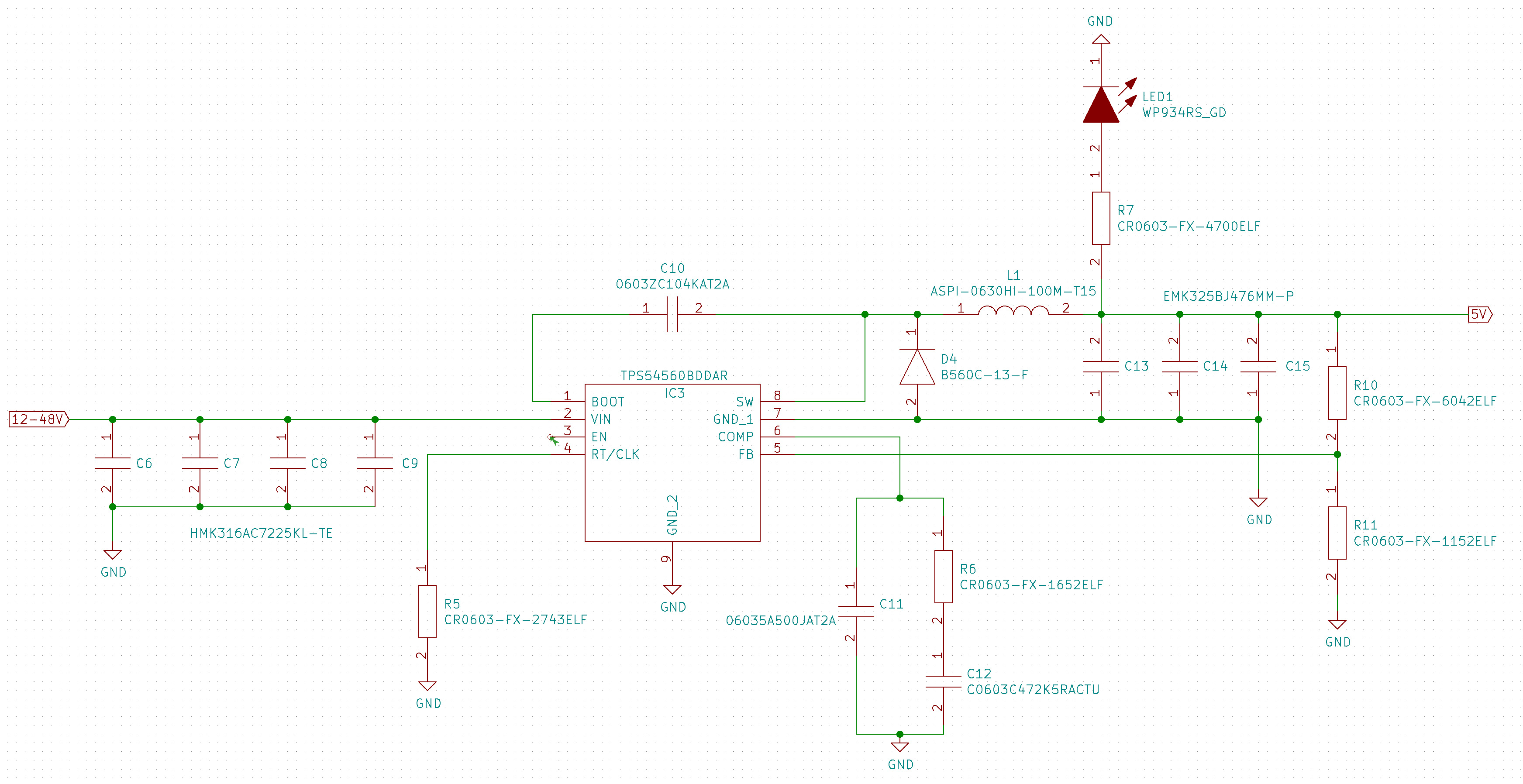
I've set up the following circuit based (almost exactly) on your recommendations in the data sheets and webench. There are only ceramic capacitors in use. The load behind it needs Vout=5V (RFID reader module: UHF, max 33 dBm RF output, max 2.2 A).

Applying Vin=9V everything works great. The load has full functionality.

When applying Vin=50V the inductor squeaks, but I can measure Vout=5V as long as the load is "idle". Sending simple commands (connection setup, settings, etc.) to the reader module is also possible. But once the reader starts reading, Vout instantly drops to 2.9V to 3.2V, lots of buzzing variety from the inductor appears and nothing can be read at the load module. (no matter the reader module setting: 1dBm or 33 dBm)

I've went through the data sheet for quite some time and switching frequency, delta_I and capacitors should actually be good enough to handle it. Especially since it works for Vin=9V.

What am I doing wrong?

Best regards from Hamburg,

Moritz

  • Hi Moritz,

    Do you know what is the value for:

    1) R5 --> Switching frequency resistor? What is your desired switching frequency?

    2) What are the voltage rating for output capacitor (47uF)?

    3) Are you referring to figure 33 on the datasheet? 

    www.ti.com/.../slvsbn0c.pdf

    4) If yes, what is the value for your C11?

    Do you have the switch node waveform on oscilloscope?

    Also is the design ok at other VIN such as 12V or 24V?

    Seems like you may have stability issue or you can also check the on time for the SW node and make sure that it is greater than the minimum on time for the part (135ns). 

    Here is what we have on our evaluation module and you can compare whether the output capacitor on your design does not derate with voltage

    Thanks

  • Thank you for taking the time.

    1. Originally R5=274kOhm.

    The regulator now works for all Vin if I put R5=820 kOhm. I guess this results in a switching frequency of about 120 kHz.

    Unfortunately, the inductor keeps buzzing (audible noise) extremely loud. It's not just a tiny buzz you can hear if everything is quite. It rather sounds like rattling. Especially when my load (RFID reader) starts scanning. It scans like 5 times per second and I can literally hear those 5 times of load transient response in between the rest of the buzzing.

    I now ordered different inductors to see if the problem persists.

    2. The voltage rating for the ouput capacitors (3x47uF) is 16V. In accordance to Vout=5V this should be alright.

    3. Yes I am referring to that figure. But I also looked into the WEBENCH POWER DESIGNER. It has the very similar TPS54560BQDDARQ1 listed. I attached a picture of its schematic. It's interesting that the power planner suggests a maximum ESR of 27 mOhm for the inductor. Mine now has like 60 mOhm. I believed it wouldn't make much of a difference for my application. But I shall see once I receive the new inductors.

    ***WEBENCH POWER DESIGNER***

    4. C11=50 pF.

    5. Unfortunately, I don't have the switch node waveform on oscilloscope.

    Do you have any other suggestions of what I can do to increase stability?


  • Hi,

    The DCR of inductor difference between 27mohm and 60mohm should not be an issue. 

    Another thing that you could try is to increase the output capacitor. 

    By any chance do you have the layout for your design?


    It is quite important to keep the input capacitor close to the input pin of the pin

    You can see the example layout here

    Thanks

    -Arief

  • Hi,

    I hope you have resolved your issue. In the meantime i will close the thread for now. 
    Feel free to re-opened it if you have any further questions. 

    Thanks

    -Arief