This thread has been locked.

If you have a related question, please click the "Ask a related question" button in the top right corner. The newly created question will be automatically linked to this question.

UCD3138: Questions of source/sink of I/O

Part Number: UCD3138

Hi E2E,

Questions below:

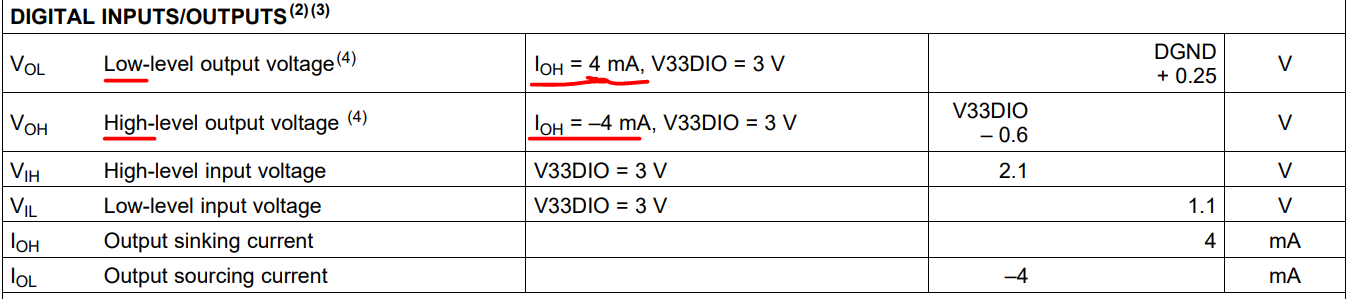
1. The datasheet defines "IOH" as sink current, but positive; And "IOL" as source current, but negative. Why does it make me think these two are mixed?

Typically, when we say source, it is positive current going outside; When we say sink, it is negative current going inside. Please help point out where I'm wrong.

2. When we talk about high/low level of I/O, why we need to define specific "IOH" value at the same time?

Does it mean that, if load is light("IOH" is low), the threshold will change?

3. If I want to test the dynamic load capability of I/O(such as checking the edge timing of square waveform), do you have any circuit recommendation?

  • Hello,

    1, the sink current means current flow into the pin, source current means current flow out of the pin, this is all you need to know, the positive/negative sign is just what we used to indicate the direction.

    2, VOL and VOH mean when the pin is configured as OUTPUT, how high and how low the signal can be, they are not thresholds. IOH is used for the test condition.

    3, the GPIO pin is for logic purpose, it should not be used to drive load, it max sink/source current is 4mA. 

  • 1. Okay, so that the direction means the current going into the IC, not going outside.

    2. Actually I'm saying that for different load current of IOH(even they're very low, but 100uA must differ from 4mA), the high and low voltage level will change, right?

    It depends on the internal PMOS+NMOS electrical features, as in my understanding.

    3. Agree, but again, 100uA and 4mA will differ. That's why I ask for it.

    For example, sending PWM for driving a opto-coupler is totally different from drving a digital isolator, from timing perspective. Not even load current but also effective input capacitor are both different.

  • hello, the GPIO outputs are push/pull outputs meaning a FET pulls up to supply or down to ground.  FET switch is effectively a resistor (Rds).  The amount of current passing through the FET creates a I*R voltage drop. With a smaller IOH current, the I*R voltage drop will decrease, so VOL will be closer to DGND, and VOH will be closer to V33DIO