This thread has been locked.

If you have a related question, please click the "Ask a related question" button in the top right corner. The newly created question will be automatically linked to this question.

Low Power System and Single Cell Battery Charging (Battery Charger, Fuel Gauge, +MPPT, +PowerPath, +SolarPanel, +USB, +DCInput)

Other Parts Discussed in Thread: BQ24650, BQ27Z561, BQ25895, TPS63802, BQ25792

Hi,

I have a low power system. The system needs 3.3V. I am using a single cell battery (1S).

I'm trying to set up a circuit for the power part. I need a low price solution.

The features I want on the power side:
    The system needs 3.3V [LDO/Buck/Switching]
    I want to charge the battery and power the system with USB and 9V/12V (if possible 9-28V) external power supply input (DC input). [LDO/Buck/Switching]
    I want to charge the battery with 4.2V/2A (or max 8hours), using USB and external DC adapter. [Battery Charger]
    The system should have an solar panel input (+MPPT feature). [Battery Charger]
    The system should have dead battery protection. When the battery dies, the system should continue working (+powerpath feature). [Battery Charger]
    I also want to measure the battery capacity using current and voltage values. [Fuel Gauge]

My Single Cell Battery (1S):
    Capacity: 5000mAh
    Charge: 2.4A (standard), CC-CV
    Voltage: min2.5V nom3.6V max4.2V
    
My system features:
    The system maximum current 2.1 A (peak 2.7A).
    The system will generally operate with microampere levels of current.
    The system works with 3.3V.
    
Based on these features, can you recommend single cell battery charger IC, 3V3 output IC, fuel gauge IC ? Or could you suggest me any other way ?

Thanks have a good day.

  • Hello,

    I have assigned this to application engineer that can help.

    Sincerely,

    Wyatt Keller

  • Hi user,

    Here are some parts that may work for you here:

    Charger: bq24650

    Gauge: BQ27Z561

    For 3.3V rail you would need buck-boost if your battery min is 2.5V

    Best regards,

  • Thanks for answer. I'm looking for a different charger.

    I have 2 more questions.

    What is the quiescent current value for BQ25895 without charger input voltage (Vbus) ?

    BQ25895 system voltage is displayed between 3.5V and 4.2V, (SYS 3.5 - 4.2), is this an adjustable value ?

    BQ25895 https://www.ti.com/lit/ds/symlink/bq25895.pdf

    Thanks in advance.

  • Hi,

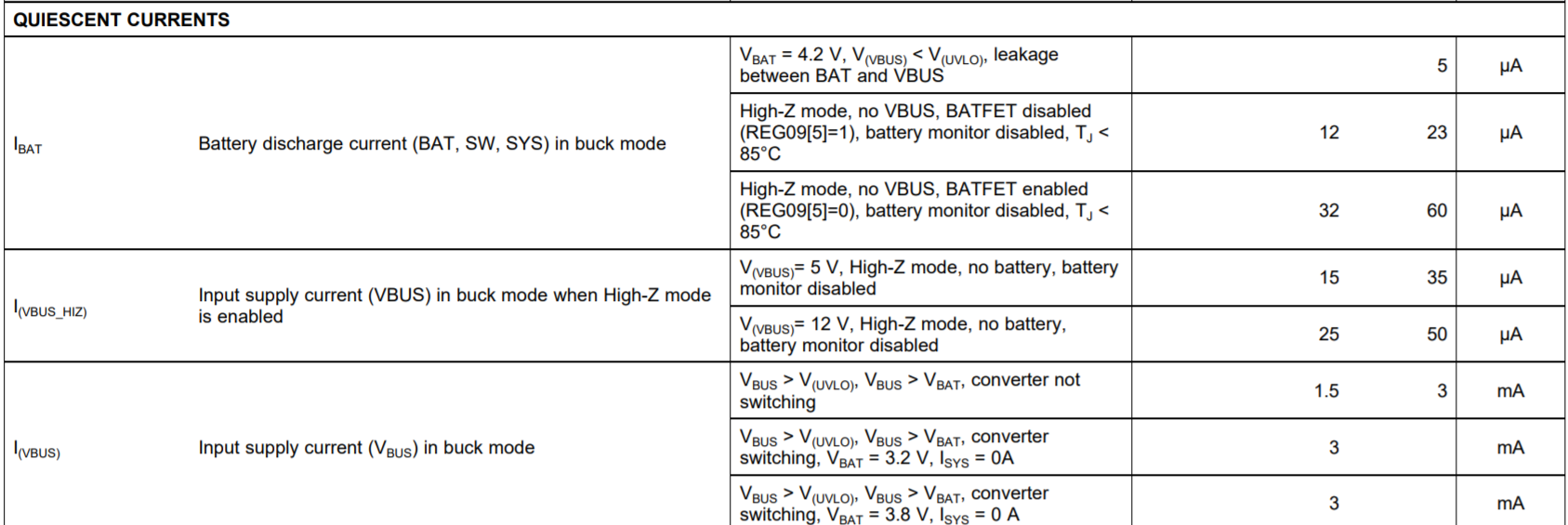
    All of TI's NVDC power path charger's have SYS output that provides MINSYS voltage, when the battery is low, and then follows the battery voltage up to regulation (4.2V for typical LiIon battery).  The MINSYS voltage (when battery is below this voltage) is adjustable from 3.0V to 3.7V  If you need 3.3V output then you must add a buck converter following the SYS output.  THe BQ25895 is controlled by host software via I2C. The BQ25895 Iq(VBUS) when switching is 3mA but drops to 23uA max if when VBUS voltage is removed or HiZ is forced using I2C.   There is a MPPT reference design for solar panel input at the link below:

    Regards,

    Jeff

  • Hi Jeff,

    Thanks for answer.


    Q1:  I will add TPS63802 (3.3V output) converter following the SYS output and configure I2C MINSYS voltage as 3.0V. So I will get 3.3 constant voltage in the system. As long as the battery voltage does not fall below 3.0 V, the quiescent current will be at the level of uA. Is it right ?

    Q2: Finally, can I connect two batteries in parallel and charge them with the BQ25895 charger IC? Does this pose any problem? Is it a problem to connect batteries in parallel for low power projects? Or should I place a charger like BQ25792 (typical application shows series connection) or a different BMS circuit?

    Thanks in advance.

    Regards,

    Halis

  • Hi,

    Regarding Q1, it depends. The Iq values for VBUS and BAT are shown below.  When in HiZ mode, the values for each are in the uA range.  When their is a power source at VBUS and the buck converter is switching, the Iq value is also shown below.  If there is a load on your 3.3V value, the current into VBUS (up to the current limit you set) and/or current out of the battery will increase to provide power to the buck-boost converter at SYS.

    Regarding Q2, there is no issue placing two LiIon batteries in parallel as they will self balance.  In your application, keeping the input voltage to the buck- boost converter no higher than 4.2V will keep it running at high efficiency.

    Regards,

    Jeff