This thread has been locked.

If you have a related question, please click the "Ask a related question" button in the top right corner. The newly created question will be automatically linked to this question.

LM5176: LM5176 is controlled by external constant current circuit. Connect to FB pin or COMP pin?

Part Number: LM5176

Dear TI Expert:

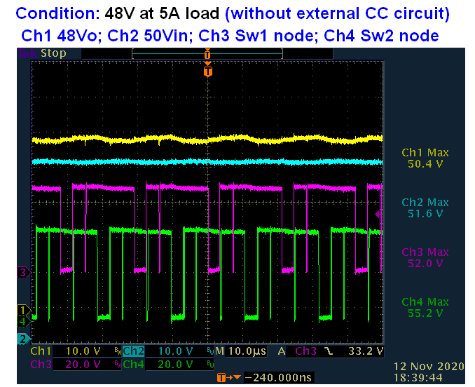
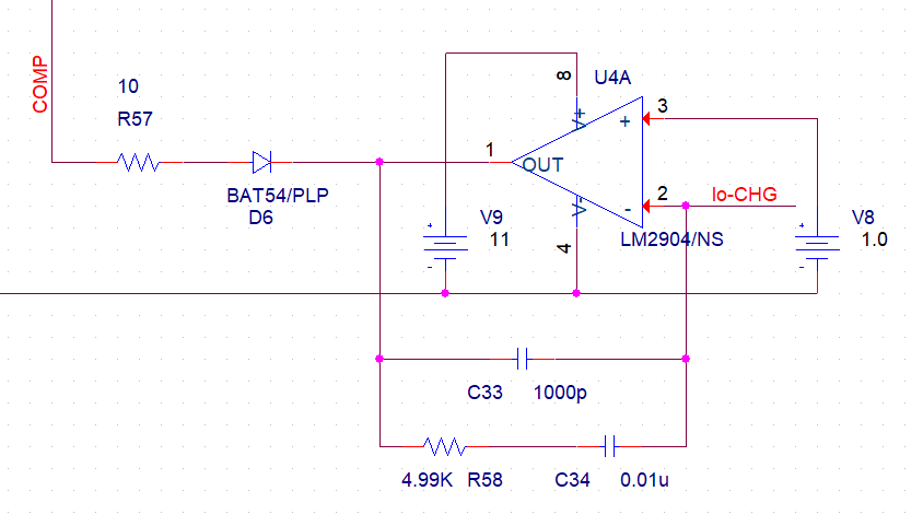
This converter (LM5176) charge to battery pack, so the constant current level shall be modified by external micro-controller. So the ISNS function of LM5176 is disable by Rsns=0ohm.

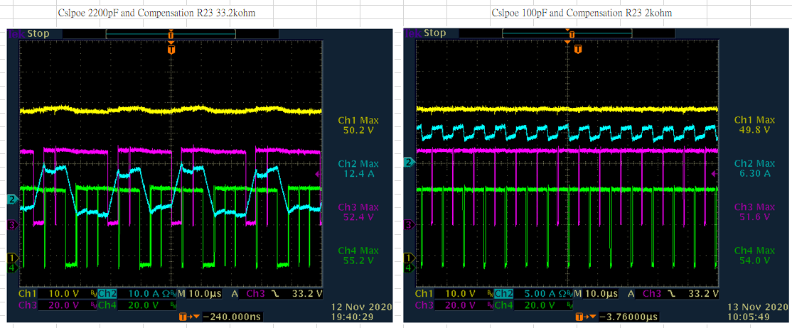
I simulated the circuit by TI tool and the simulated result is good. But the real test is not good (LM5176 is damaged. The resistor 2.2ohm is open.)

Question:

1) Shall the external constant current be connected to pin 9 COMP or pin 11 FB?

Now it is connect to pin9 comp. But the LM5176 is damaged during constant current mode.

Is there anything I should know?

BTW, the another reason that disable ISNS function is GM error amplifier of LM5176. Base on LM5176 datasheet Equation-7, the disable ISNS function is good for increase the maximum Vin range for buck operation.

Thanks.

Aska

  • Hello Aska,

    Would you please share your complete schematic?

    For an external regulation, using COMP pin is a good solution as long as you make sure that the voltage on COMP stays within the abs max rating.

    Where did you connect FB to?

    Did you disable the ISNS function or the CS function?

    You could use the device as well in the configuration given in this reference design, but would need to add your circuit to the ISNS funtion: 

  • Dear Brigitte:

    Thanks for your feedback quickly.

    Answer you first.

    1) Before pcb layout, I check it in simulation. The external constant current circuit doesn't work while connect to FB pin. So the external CC circuit connect to COMP. 

    2) Only disable ISNS function by Rsns 0ohm. But keep CS function (Rcs 5mohm).

    3) Refer your attached file. INA301A2 is not ok for me. It is only 36V supply. My battery voltage is 48V level. Is there any similar part good for me?

    I could sent the schematic to you but pls give me the mail address.

    Thanks.

    Aska

  • Dear TI Expert:

    LM5176 is not robust part while I am testing.

    Many time it was damaged during it is working. I have no idea how to modify it.

    I always found the SS pin impedance of LM5176 is not normal. No damage in power mosfet. After replace LM5176 by new one, it works again.

    Could you please review the circuit and give me some suggestion?

    The input voltage is 48.5V to 50V. And Vo shall be 48V with 5A load rating.

    Is there any TI IC cant support the condition? Please advise it. LM5176 is not good solution for me.

    Thanks.

    Aska

    CC to COMP 2A5 constant_20201110.pdf


  • BTW, I already removed the external constant current.

    LM5176 is also not stable while Vin is very close to Vout.

  • Hello Aska,

    I am sorry, that you experience not the expected behavior.

    I am not able to review the schematic today in detail, but at the first glance, it seems that the compensation might get adjusted.

    I will check it tomorrow. In the meantime you could check the compensation with the quick start calculator you find in the product folder on our website.

  • Dear Brigitte:

    Sure, I have calculated the compensation by TI quick start tool.

    <Inductor 10uH>

    The recommend inductor is 2.3uH. The current inductor is 10uH. I also tried to different inductance to see any improvement. (4.5uH/1.6uH). No big deal.

    According LM5176 page18 Equation7, it means "Large L1, higher Cslope, smaller Rsense and higher Fsw can increase the maximum Vin range for buck operation."

    For Vin range is 48.5V~52.5V and vo is 48V, I chose the 10uH for inductor. Cslope is calculated by TI tool. Rsense is 0ohm due to disable average current limit and enable external constant current circuit.

    Wait for your suggestion.

    Thanks

    Aska

  • Dear TI Expert:

    Modified items:

    1) ISNS- and ISNS+ both connect to Gnd. (Disconnect from Rsen2)

    2) Rsw (low side Rshunt) is changed from 5mohm to 2mohm.

    3) Cslope is changed from 680pF to 2200pF by TI quick start tool for Rsw=2mohm. 

    Quickly updated after some modified items:

    <i> Disable external constant current circuit:

    • The output voltage can supply 48V/5A successfully. The Vo can maintain on 47.8V at 5A load. ==> I guess the previous test is trigger by cycle-by-cycle current limit. Then LM5176 is damaged on this condition.

    <ii> Enable external constant current circuit:

    • While the constant current setpoint is decreased to limit the current, the Vout is drop with reducing current. During adjust the CC setpoint slowly, the Vout is disappeared. While I power up it again, the Vo is only 40V and switch node-2(near output voltage) is deformation. ==> Something is damaged again. I guess it shall be LM5176. 

    Thanks.

    Aska

    CC to COMP 2A5 constant_20201112.pdf

  • Hello Aska,

    Thank you very much for the update.

    Why did you change R7 to 2 mOhm? The recommended sense resistance for 5A output current is in the range of 13 mOhm, so the output voltage should be regulated properly with the 5 mOhm you used before.

    With Rsn2 set to 1 mOhm, the average output current is set to a limit of 50A, so it should not limit the current at all in the application.

    Please keep the slope capacitor at 100pF for the moment, in general lower slope capacitor is better.

    Please let's find out first, why you need to reduce R7 to get the full output power when the ISNS+/- pins are shorted.

    Please measure the input voltage, output voltage and switch nodes if possible in one scope plot. In addition the gate drive signals would be interesting (please keep in mind to reference the HDRVx signals to the SWx signals).

  • Dear Brigitte:

    Answer your questions first.

    1)R7 (Rsw) change to 2mohm

    The original value is 5mohm for 16A setting. It is only to avoid any surprise during testing it.

    I try to verify the LM5176 ISNS+/- function, so rework the ISNS+/- sense to output Rshunt (Rsn1).

    While it can be trigger at my setpoint(2.5A), the current can be reduced by ISNS function. But I found it sometimes is trigger by cycle-by-cycle current limit during the output current is reduced to 1.9A. I guess the pervious test shall be trigger by noise.

    That is why I change the R7(Rsw) to 2mohm. Finally I got the good result.

    2) Cslope 100pF

    That's mean I shall not use the value by TI quick start tool?

    3) ISNS+/- short to Gnd

    I need the constant current setpoint can be adjust by external control, so I disable the ISNS+/- function.

    In LM5176 datasheet, the ISNS+/- function can be disabled by short. That is why it is short to Gnd.

    BTW, I will measure the signal as you want. Provide it later after I repair it.

    Thanks.

    Aska

  • Dear Brigitte:

    Attached is the waveform. It is only LM5176 converter w/o external constant current circuit.

    1) By previous damaged test (enable external cc circuit), the damaged component is only LM5176.

    2) Switch node is not square waveform due to the high/low side mosfets turn-on in short period. But I don't know why.

    Thanks,

    Aska

    Sw1 node is the first leg of inductor (the switch node of buck mode)

    Sw2 node is the 2nd leg of inductor (the switch node of boost mode)


  • Hello Aska,

    Would you please try 100pF for the slope compensation and reduce R23 to 2k?

  • Dear Brigitte:

    That is amazing. The switch node waveform is pretty good. (right side picture).

    Could you please let me know what problem is?

    Is there anything shall be careful while I modify the circuit?

    Next step, I will try R7 (Rsw) back to 5mohm. If it is ok, I would like to set the cycle-by-cycle current limit lower.

    But my priority is the LM5176 is controlled by external constant current circuit.

    Thanks.

    Aska  

    P.S Both waveforms are tested on 48V/5A load.

  • Hello Aska,

    The reduced COMP resistor reduces the crossover frequency and make the converter less sensitive to noise in the system but reduces as well the reaction speed on load or line transients. So you need to check if the transient response is still fast enough for your system.

    The reduced slope capacitor reduces as well the noise sensitivity.

    In general a switch mode power converter needs to have a crossover frequency as low as possible for the system needs to make it maximum stable.

  • Dear Brigitte:

    Appreciated you so much.

    Finally, it is fixed for adjust constant current by external circuit.

    Thanks for your reply.

    Aska