This thread has been locked.

If you have a related question, please click the "Ask a related question" button in the top right corner. The newly created question will be automatically linked to this question.

TPS2373-4EVM-758: Flyback Transformer Secondary Side - Heating Issue in the Snubber Circuit Resistor

Part Number: TPS2373-4EVM-758
Other Parts Discussed in Thread: TIDA-050023

Hi Team,

Reference design :- Class 6 Low Cost Flyback for PoE PD - TPS2373-3EVM-024

We are following same reference design for our PoE section and observed heating issue in the R47 & R48 ( 15E ) resistors in parallel with D18. The temperature measured is 65 degrees.

Attaching waveform below

1) Transformer pin 12 with respect to GND.

image.png

2) Across 15E resistor

image.png

Could you please confirm whether this is an expected behaviour or an issue?

  • Hello,

    What size is the resistor? The size is important. This resistor is dissipating power so yes we expect it to get hotter than other components. But if it is too small it will get hotter.

    If this post answers your question, please indicate so by marking this thread as resolved. Thank you.


    Regards, 


    Michael P.

    Applications Engineer

    Texas Instruments 

  • Hi Michael,

    The resistor size is 2512 same as reference design.

    Is there any way by which we can reduce the temperature of this component as the board temperature is going up due to this ? Please advise.

  • Hello 

    Is this during full load? 

    When compared to our reference design, 65 degrees is lower than what we see as far as highest temp on board. 


    To decrease thermals, add more copper for these parts to dissipate heat. The resistor size is large enough to not be a contributing factor. You could also consider a heat sink.

    If this post answers your question, please indicate so by marking this thread as resolved. Thank you.


    Regards, 


    Michael P.

    Applications Engineer

    Texas Instruments 

  • Hi Michael,

    The maximum temperature is accepted by the customer. 

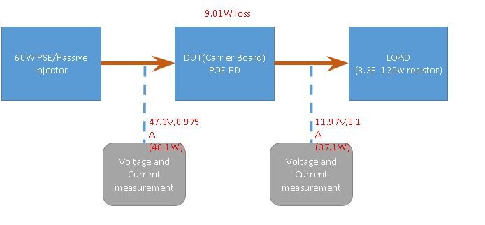
    We have an observation when powered our board with 60W PSE and connected a load on the output of the POE section. We observed a power loss of 9.01W on our board.

    Following are the observations.
    image.png
    This is our test method :-
    Please let me know your comments on this.

  • Hello,

    9/60 = 0.15 --> so the design is about 85% efficient at 77% load capacity. That is not far from the TIDA-050023. Please review the test report and let me know if you have any other questions!

    Also, for new questions, can you please create a new thread on E2E? Thanks!

    If this post answers your question, please indicate so by marking this thread as resolved. Thank you.


    Regards, 


    Michael P.

    Applications Engineer

    Texas Instruments