This thread has been locked.

If you have a related question, please click the "Ask a related question" button in the top right corner. The newly created question will be automatically linked to this question.

TPS92515HV-Q1: TPS92515HV-Q1

Part Number: TPS92515HV-Q1
Other Parts Discussed in Thread: TPS92515

Hi,

I am using TPS92515HVQDGQRQ1 in my design. These are the required parameters.

Vin = 12V

Vout = 9.3V (3LEDs in series each of 3.1 forward voltage)

Iout= 1A

I have implemented the circuit using TPS92515HVQDGQRQ1 but not able to achieve desired output. One thing I noticed is the Output average voltage (measured across output capacitor) is 5V and the switching frequency I could measure is 21Hz. 

I have attached the snapshot of the design. It will be helpful if I get any suggestion on how to increase the switching frequency.

For now I have tied the PWM1 to VCC and Isolated the load by disabling the load switch (TPS22810TDBVRQ1).

Regards,

Muhammed Shajih

  • Please refer to this attachment if image is not visible.

  • Hello,

    Your schematic looks good.

    Are you sure there is 5V at the output, VSW, if so it should be running.  Can you get oscilloscope pictures of VSW, SW, Coff and Vin?

    You may have to remove U4 since it is being supplied by VSW.  The TPS92515 is not a voltage output, it is a current output.  It also is meant to drive an LED load, if there is any other load at low voltage the output may not rise enough to start especially with C8 being 22 uF.  The maximum off-time is 230 us typical which would look like approximately 4.4 KHz switching.

    Best Regards,

  • Hi Irwin,

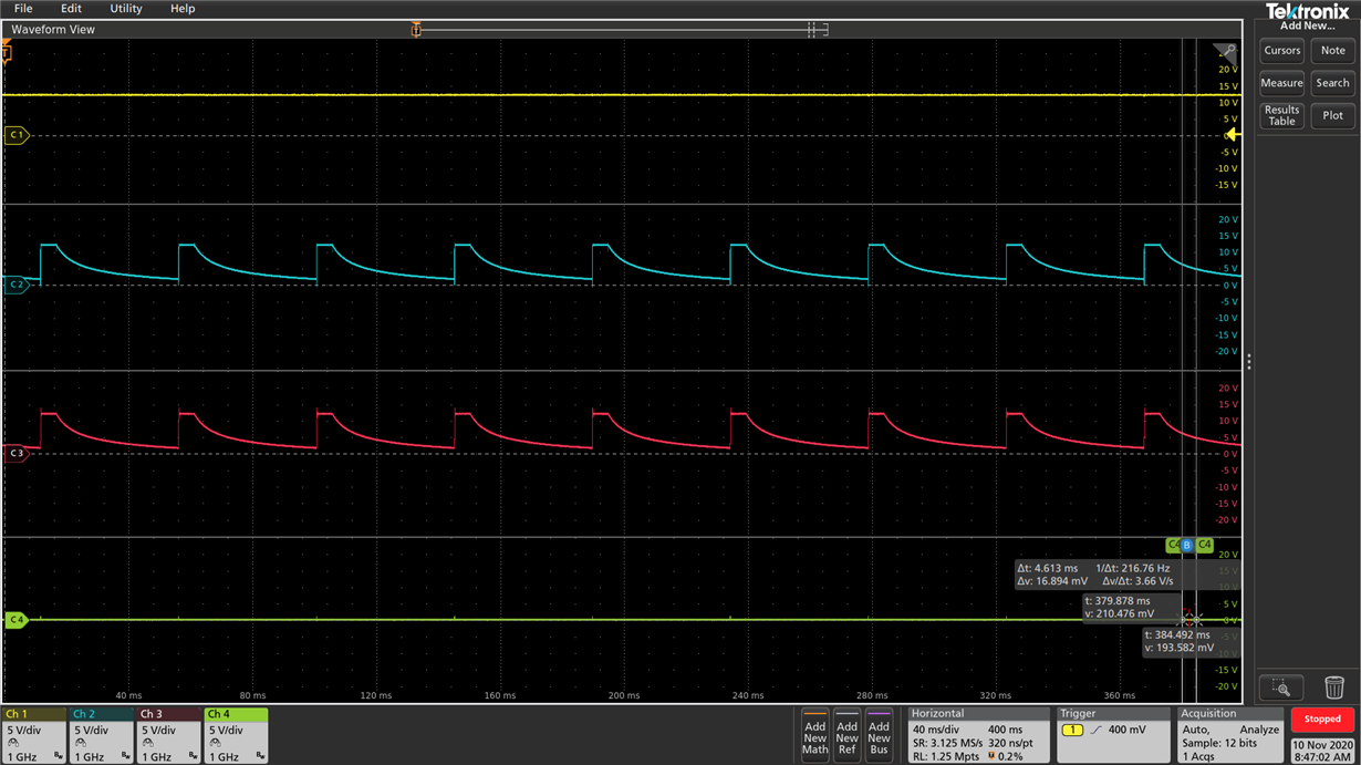
    Below are the waveform.

    Ch1: 12V

    Ch2: SW of U1

    Ch3: VSW

    Ch4: Coff of U1 According to my Schematic .

    At Coff I was not getting any signal.

    Regards,

    Muhammed Shajih

  • Hello,

    The output voltage is going to the same level as the input voltage.  The peak current threshold is not being met meaning the MOSFET is just turning on and staying on.  After a certain amount of time the boot capacitor will discharge and require a refresh.  The switch node needs to be pulled to ground by a current sink in the TPS92515.  This takes time because it has to discharge the output capacitor.  It appears that you have no load connected.  Try applying a lab supply voltage to your led string and slowly turn it up to see if it is connected correct.

    Best Regards,

  • Hi Irwin,

    In fact I have isolated the load by disabling the load switch (U4). Can I enable the load switch or I need to completely eliminate the load switch and connect directly?

  • Hello,

    There needs to be a load.  I don't know what the load switch will do if it is in the circuit so I would try removing it and connecting the LEDs direct.  Once that is working you can try other configurations to see if they work.  You can also try leaving the load switch connected and watch the waveforms as before as well.  The TPS92515 needs to be able to source current to a load that is lower voltage than the input.  It also needs the output to be able to get above 1.0V so the off-time works.  If it cannot there is method to add a second Roff for start-up issues.

    Best Regards,

  • Hi Irwin,

    Thanks a lot. It worked when I connected the load without much issues.