This thread has been locked.

If you have a related question, please click the "Ask a related question" button in the top right corner. The newly created question will be automatically linked to this question.

TPS65218D0: TPS65218D0 DCDC6 Internal Converter usage

Part Number: TPS65218D0
Other Parts Discussed in Thread: TPS65218, TPS2101, TPS65217, MSP430FR2311

My application uses a TPS65218D0 powering an AM3352BZCZD80.

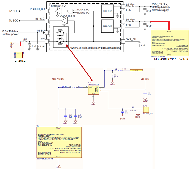
Trying a BOM cost reduction we are considering the usage of the TPS65218 internal switch as TPS2101DBVR replacement as shown in figure below.

Is there any drawback in this action?

  • The image you attached is not displaying. Please use the Insert/Edit Media button that looks like a Polaroid photo with a '+' plus sign in the lower righthand corner.

    The subject line says "DCDC6 internal converter usage", but the body of the post says "internal switch" which sounds more like a load switch (LS1, LS2, or LS3) than a switching regulator.

    DCDC6 generates 1.8V by default and is intended to work with DCDC5 (1.0V) to generate the required RTC voltages of the AM335x from either the main supply or a backup coin-cell battery.

    LS2 and LS3 could theoretically be used as a power mux similar to TPS2101 but keep in mind that LS3 is not reverse voltage protected (single FET vs. back-to-back FETs) and that these load switches must be enabled by I2C commands. They are not sequenced automatically like LS1.

    Please attach the image correctly and specify your use case so I can provide more assistance.

  • Dear Brian:
    Thanks for your response.
    Our current application uses a TPS65217 as a power management device.
    We are working on an upgrade which will use TPS65218.
    Current desgin uses TPS2101DBVR to switch MSP430FR supply voltage from VDD to cell coin battery as shown in the lower part of figure below.
    We are  planning to connect the cell coin battery and the MSP430 to TPS65218 as shown in the upper part of the figure below.
    Is this configuration feasibe?


  • Can you operate your MSP430 at 1.8V?

    The MSP430FR2311 datasheet indicates it will operate at 1.8V or 3.3V (DVCC recommended operating range is 1.8V to 3.6V), but I cannot say if your application will allow this.

    DCDC6 will always generate 1.8V by default. The feedback reference voltage at FB6 is 1.8V, and there is no internal resistor divider. Also, the maximum output current is 25 mA.

    Keep in mind that if you will use DCDC6, then the output inductor and capacitor(s) need to be populated for DCDC5. DCDC5 will generate 1.0V, which I expect will not be used in your system, but it would not be wise to leave this output floating if DCDC6 will be used.

    If you are convinced this will work in your system, then I do not see any issues. It is definitely reasonable, but keep in mind VDCDC6 = 1.8V and IOUT,max = 25mA.