Because of the holidays, TI E2E™ design support forum responses will be delayed from Dec. 25 through Jan. 2. Thank you for your patience.

This thread has been locked.

If you have a related question, please click the "Ask a related question" button in the top right corner. The newly created question will be automatically linked to this question.

LMG1020: Does the LMG1020 support continuous wave output of the laser diode?

Part Number: LMG1020

Is it possible to power the laser in continuous wave mode (i.e., turn the laser constantly on) with the LMG1020? My understanding of the driver + GaNFET is that if I supply a constant 3V-5V signal to IN+, the GaNFET will be constantly open, allowing the Vbus current to flow through the laser diode until IN+ goes low.

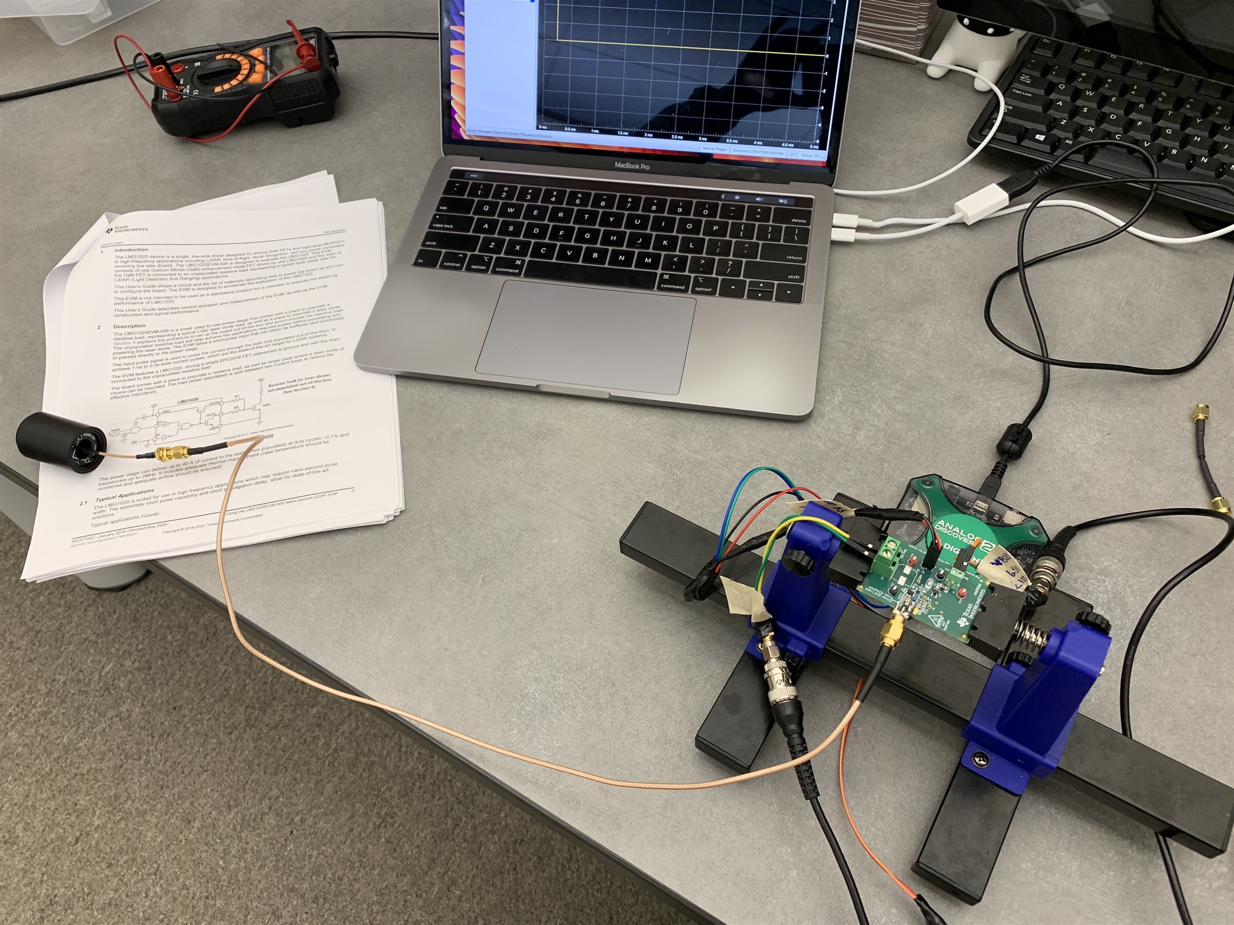
From my test setup (following the setup procedure in the design note, image attached), I was able to achieve relatively stable laser emission using a 200Hz square wave with 5% duty cycle (so 250us on pulse, then 4750us off) -- please see attached video. However, if I use a very low frequency square wave, e.g., 1Hz (so 0.5s on, 0.5s off), the laser is unable to be powered on for the full 0.5s. Furthermore, if I supply a constant IN+ voltage, the laser does not turn on at all.

So for whatever reason, it seems the driver isn’t supplying a constant current/voltage for large periods of time. It seems to work fine for short pulses with a recovery time between pulses. Is this behavior expected?

Click here to play this video

  • Hello Charles,

    Thanks for reaching out.

    Can you please share waveforms around IN+, gate, and VDD with the low frequency square wave. If the laser is not turning on during this setup, we want to monitor and follow the signal path to the laser diode to understand whether it is a driver related issue or GaN FET related.

    Regards,

    -Mamadou 

  • Hi Mamadou,

    Thank you for the reply! Here are two different setups. In each setup, I'm using the same laser diode, PLT3 520D, which has an operating voltage between 6V and 8V, and max forward current of 330mA.


    Setup 1 (Output same as shown in attached video)

    TX Freq = 200Hz, Duty Cycle = 5% (on time 0.25ms)

    Setup 2 (No visible laser diode output)

    TX Freq = 200Hz, Duty Cycle = 50% (on time 2.5ms)

    From what I've tested, if the laser is on for more than 1ms (20% duty cycle at 200Hz), the same issue happens as in setup 2.

    Thank you for the help!

    Charlie

  • Hi Charles,

    I will review the links and get back to you before COB Friday.

    Regards,

    -Mamadou

  • Hello Charlie,

    Thanks for waveforms.

    THe LMG1020EVM is typically geared toward HF applications where you might expect anywhere between 100kHz to 50MHz as specified in the user's guide. With low frequency pulses, the driver might not be pulsing the appropriate amount of the current to enable the laser, to be confirmed.

    However, I have also reviewed the laser diode datasheet and it appears that you get the peak output power with a pulse <=10us, with <50% duty cycle. I am concerned that 2ms on time might be outside of the laser diode specification.

    What is also concerning is the it appears the Vbus is shorting when operating >=20% duty cycle in which case, I'd be intrigued to find out whether the FETs or laser get damaged.

    Regards,

    -Mamadou

  • Mamadou Diallo said:

    THe LMG1020EVM is typically geared toward HF applications where you might expect anywhere between 100kHz to 50MHz as specified in the user's guide. With low frequency pulses, the driver might not be pulsing the appropriate amount of the current to enable the laser, to be confirmed.

    I see. My understanding of the circuit is that the driver doesn't supply any current to the laser, but rather only opens the FET which then supplies current to the laser from VBus.

    Mamadou Diallo said:

    However, I have also reviewed the laser diode datasheet and it appears that you get the peak output power with a pulse <=10us, with <50% duty cycle. I am concerned that 2ms on time might be outside of the laser diode specification.

    Unfortunately, I've confirmed that this laser diode can be powered in continuous wave mode (with 100mW optical output power, per the data sheet) when directly connected to the same bench top power supply. 

    Mamadou Diallo said:

    What is also concerning is the it appears the Vbus is shorting when operating >=20% duty cycle in which case, I'd be intrigued to find out whether the FETs or laser get damaged.

    Agreed, this is the strangest behavior in my opinion, and I don't understand why it's happening. That being said, the laser itself is fine (it simply turns off, since the supply voltage drops below the operating voltage) and the EVM module continues to work if the duty cycle is reduced (indicating the FET is still operating properly).

  • Charles,

    Yes correct, the driver IC is turning on the FETs allowing current flowing through laser from Vbus but as the FETs are on, it is dissipated power at its junctions which the board in general expects high frequency switching with narrow pulse widths typically.

    You may need to double check that FET is not heating throughout the on-time pulse given the duty cycle.

    Regards,

    -Mamadou

  • Mamadou Diallo said:

    Charles,

    Yes correct, the driver IC is turning on the FETs allowing current flowing through laser from Vbus but as the FETs are on, it is dissipated power at its junctions which the board in general expects high frequency switching with narrow pulse widths typically.

    You may need to double check that FET is not heating throughout the on-time pulse given the duty cycle.

    Regards,

    -Mamadou

    Would a good next step be to check the temperature of the FET under various duty cycles, and report back the results here?

  • We have checked the gate driver IN and OUT, VDD signals, no apparent issues there. The next logical steps would be a checking MOSFETs junction temperature given that the bus voltage is shorting at higher duty cycles.

    If not the FETs are the issue, I suggest populating the C5 which should not have been on the board by default. Given the long duration operation, we may try increasing the bus caps to see if there is any improvement. Kindly ensure that the cap you use have sufficient margin to handle bus operation and should have similar voltage derating. 

    Regards,

    -Mamadou

  • Sounds good, I'll populate C5 and report back. Do you have any recommendations for the cap value?

  • Hi, Charles,

    C5 should be Capacitor, aluminum, 4.7 µF, 100 V, ±20%, SMD

    For example, UUX2A4R7MCL1GS

    I quickly reviewed this thread, and from your post on Wednesday, it seems the LMG1020 is providing a proper gate signal to the GaNFET. It sounds like maybe your supply is collapsing, and that's what's causing the issue. As Mamadou mentioned above, check the current capability of your laser diode, without any limiting resistance in the circuit, you may draw too much current and damage the laser diode. It seems you are drawing more than 500 mA from your supply causing it to go into constant current mode, and dropping the output voltage.

  • Don Dapkus said:

    Hi, Charles,

    C5 should be Capacitor, aluminum, 4.7 µF, 100 V, ±20%, SMD

    For example, UUX2A4R7MCL1GS

    I quickly reviewed this thread, and from your post on Wednesday, it seems the LMG1020 is providing a proper gate signal to the GaNFET. It sounds like maybe your supply is collapsing, and that's what's causing the issue. As Mamadou mentioned above, check the current capability of your laser diode, without any limiting resistance in the circuit, you may draw too much current and damage the laser diode. It seems you are drawing more than 500 mA from your supply causing it to go into constant current mode, and dropping the output voltage.

    Hi Don,

    Thanks for the response, and apologies for the delay. I agree, it appears that the supply was collapsing under a heavy supply. However, the situation got weirder! I was testing a few other LMG1020EVM drivers, and was able to drive the laser at 100% duty cycle without the supply collapsing. More importantly, I think I figured out the issue with the first driver: a short between the anode and cathode pins. Specifically, I tested the resistance between the cathode and right anode pad, and saw that the resistance was only a few ohms. I wasn't able to see any shorts on the surface, however I suspect the SMA adapter might've scratched some of the solder mask away. Consequently, I think the red trace in the circled area was bridging the anode and cathode together:

    This probably isn't recommended, but I ended up cutting a groove into the PCB where each "X" mark is. Anyways, everything's now working properly!

    Also, one (slightly tangential) thing I've been wanting to mention: the EVM user's guide mentions in multiple places (including the schematic) that R5-R8 are not populated out of the box:

    When using LMG1020EVM out-of-the-box, the resistor load, R5 - R8, is not populated.

    However, in the four EVMs that I've tested, R5-R8 is populated on all of them! Not a big issue, just a little inconsistent with the user's guide.