Hello all,
I am struggling with a weird behavior on all of my 4 Testboards including a TPS62402 step down converter to provide me with 3.3V and 1.8V for my peripherals.
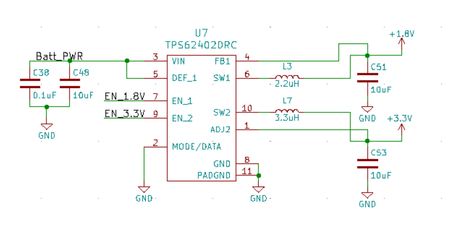
My hardware setup looks like this:
- host MCU Nordic nrf52 (directly powered through the battery)
- TPS62402
- VLSI VS1063 (powered through the TPS with 1.8V and 3.3V)
- SD Card (powered through the TPS with 3.3V)
- RTOS mbedOS
When I am pulling EN1 and EN2 up I am getting the desired 1.8V on Converter 1 and 3.3V on Converter 2. All fine so far but when I am pulling the EN pins down I am getting the following results:
- EN1 (measured on the TPS 0.01V) -> Converter 1 is OFF (output 0.0V)
- EN2 (measured on the TPS 0.04V) -> Converter 2 is still providing output between 1.765V and 2.65V measured on Pin 10.
I could not find any explanation in the datasheet. First I thought it might be a hardware issue related to some other part leaking voltage into the 3.3V rail so I have tried another one of my custom test boards with the same result. I have the same behavior on all of my boards that include the TPS62402.
My second attempt was to make sure that no other device is providing any current through the (battery powered) host MCU pins so I set all PINs as input and pulled them low. With this approach I am still reading around 1.375V on the TPS converter 2 output.
Is there any obvious explanation that I am missing why I can still measure the mentioned voltage on the TPS? I refuse to believe that all parts are defective. I have attached the schematic part including the TPS62402 hoping that the solution might be obvious.
Thank you already for any hint/help.
Best