(We modify the capacitance and resistance value on the LM5176EVM )
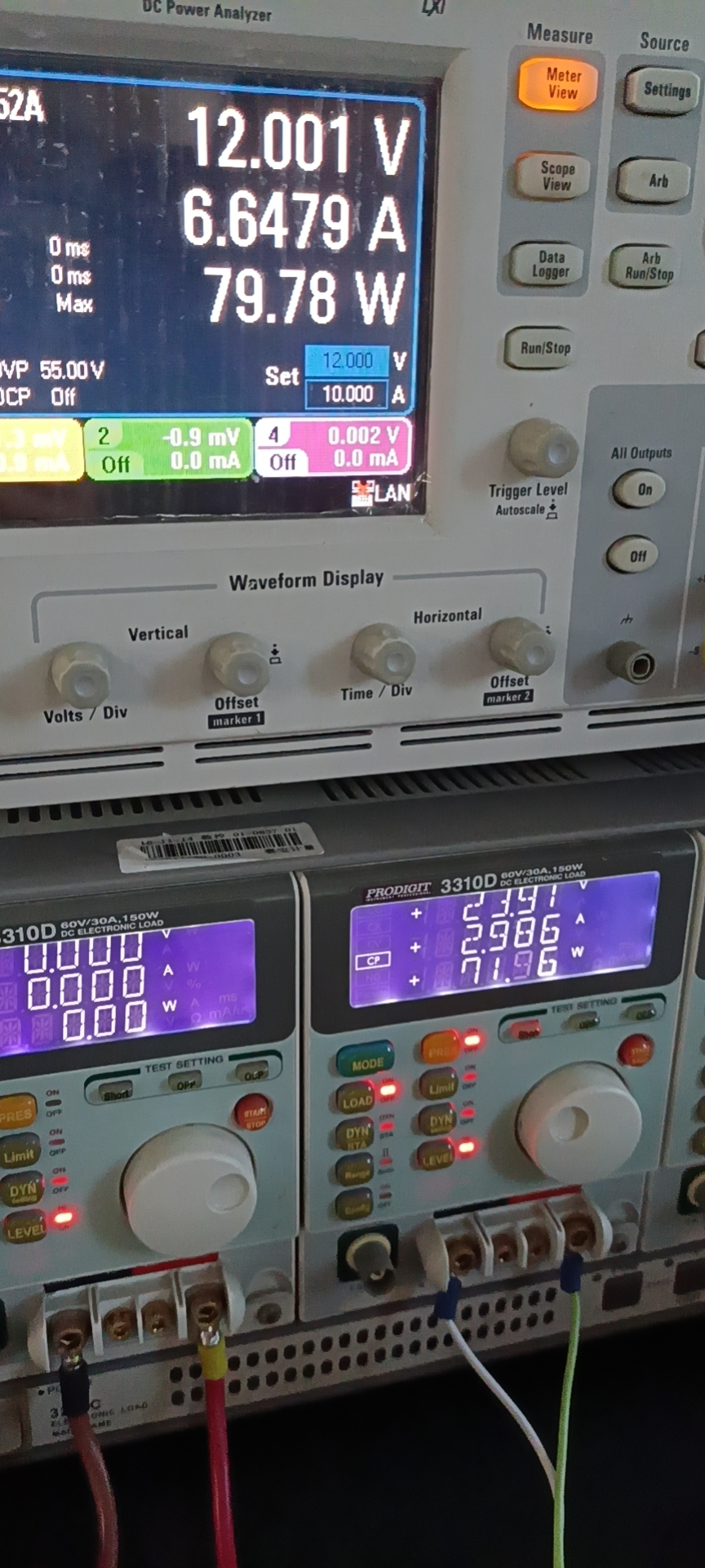
We changed the feedback resistance to: R11=100k, R14=475K. Our Vin=24V /Vin=12V ,My customer’s goal is that when the input is Vin=24V/Vin=12V, the efficiency can reach more than 95%(vout=24V@3A) the data sheet, this value can be achieved)But when I was testing, I found the following problems:
1.Insufficient efficiency
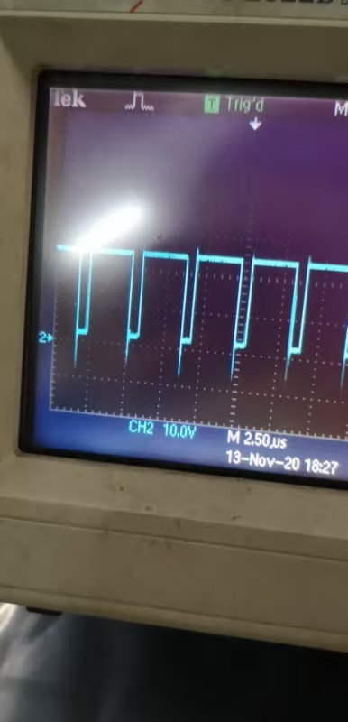
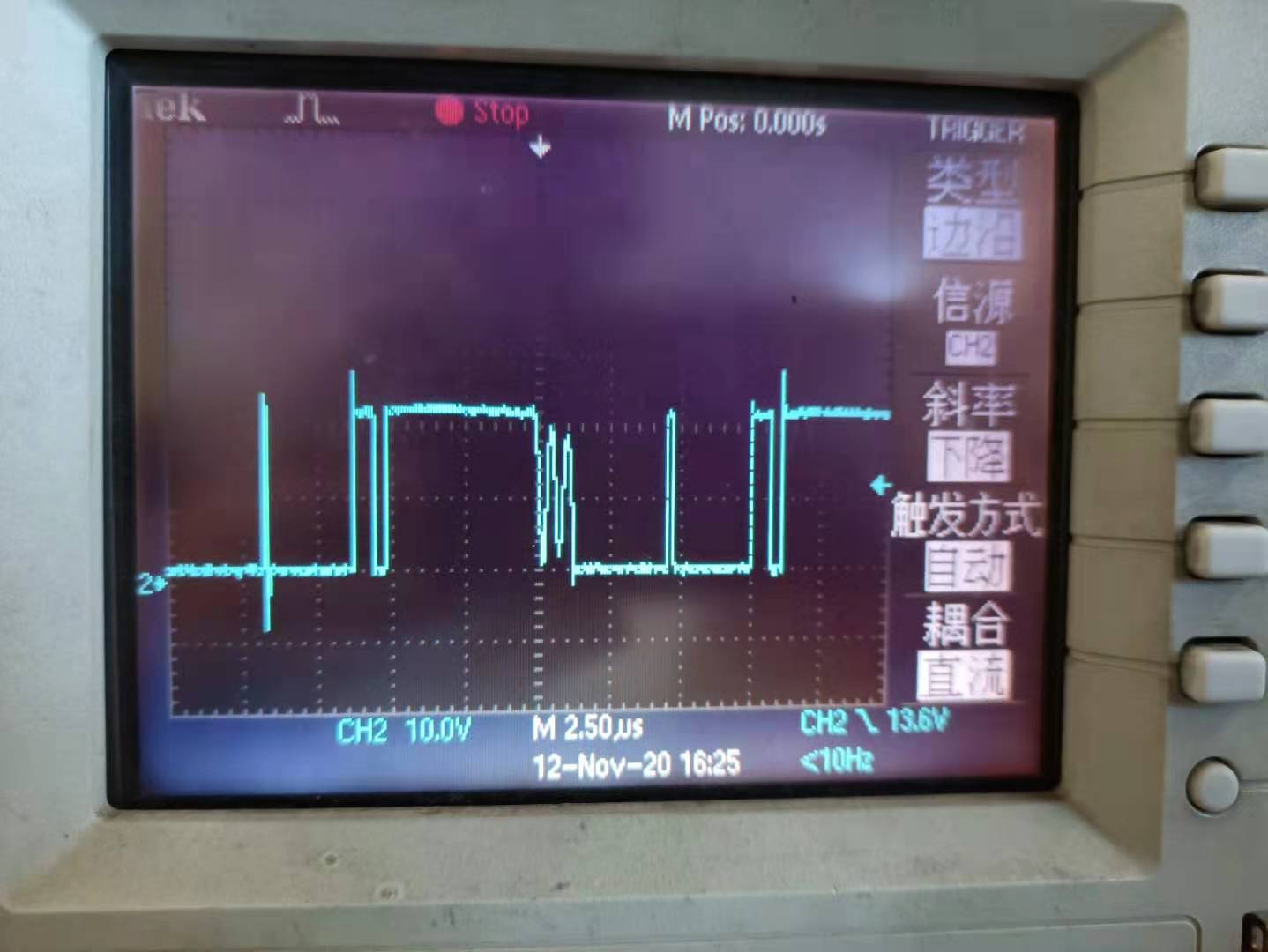
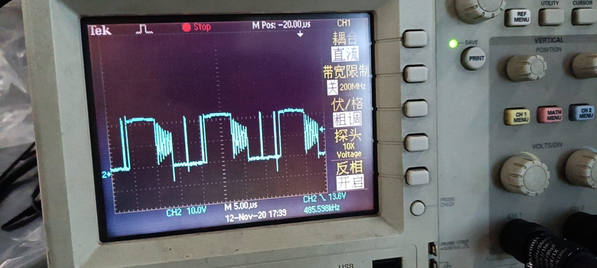
2.Abnormal waveform
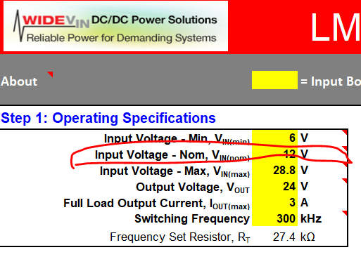
- When I set the voltage nominal value to 24V,Inductance does not change,The output capacitance is 684uf (4.7uf*5 ceramic capacitor +330uf electrolytic capacitor,We estimate ESR to be 2 m ohms) ,The MOS is: BSC093N04LS.We use the calculation tool to get the result:

We set up according to him, but the result is not ideal.I found that the efficiency can reach 96% at 24 to 24@3A, but at 12 to 24@3A, the efficiency will drop to about 92%, and the SW waveform is abnormal
- When I set the voltage nominal value to 12V,Inductance does not change,The output capacitance is 684uf (4.7uf*5 ceramic capacitor +330uf electrolytic capacitor,We estimate ESR to be 2 m ohms) ,The MOS is: BSC093N04LS.We use the calculation tool to get the result
when 24 to 24@3A The SW waveform is abnormal and the efficiency drops to 94%
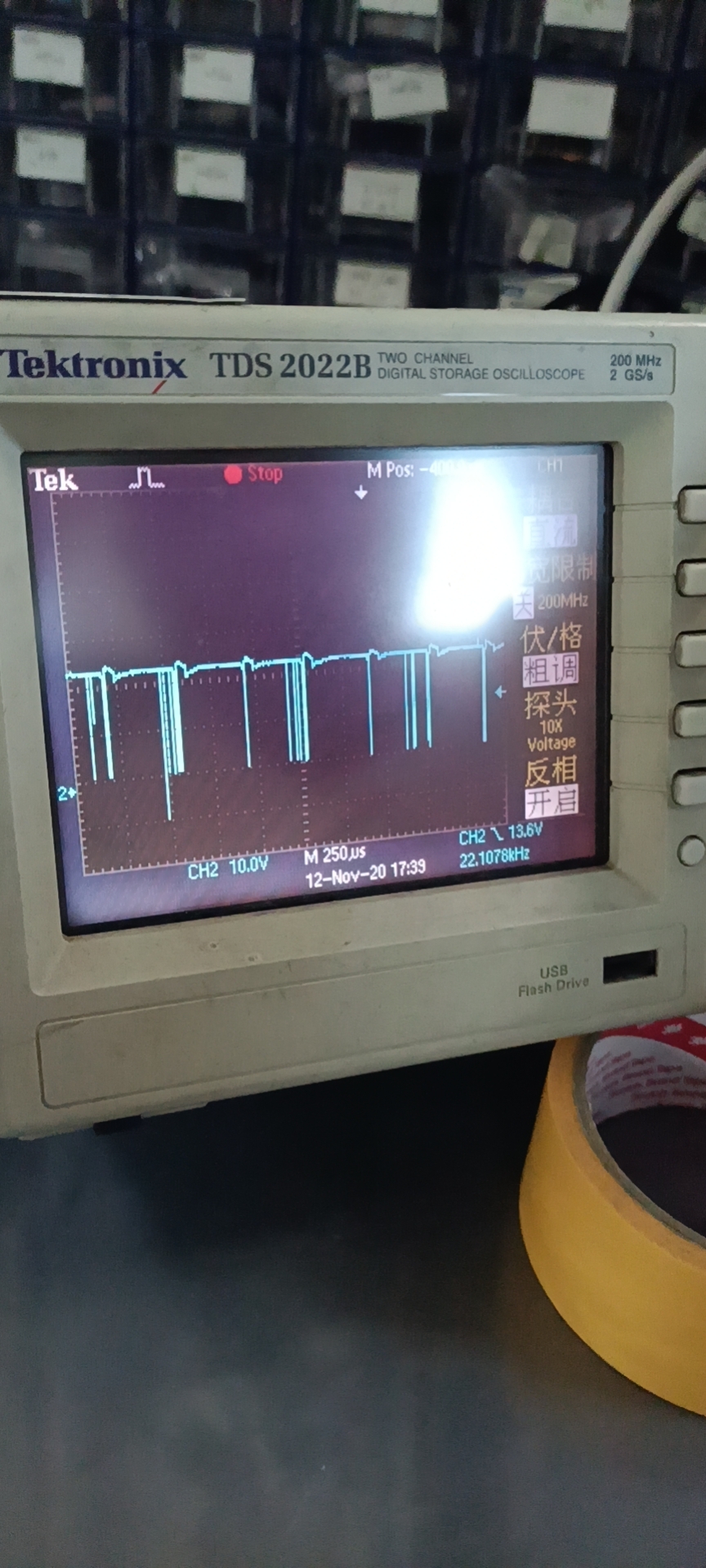
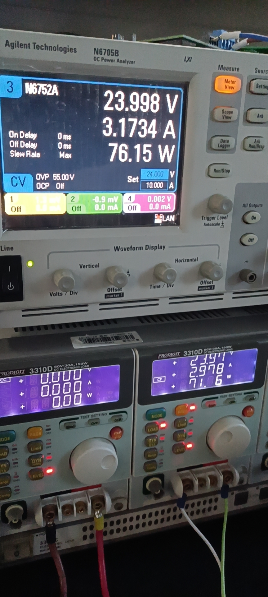
when 12 Vto 24@3A The SW waveform is abnormal and the efficiency drops to 90%
So I have the following questions:
- Why is the SW waveform abnormal? How should I set my voltage normal to 12/24V?

- How should I set up to make my efficiency higher? (I think the switching loss caused by the abnormal SW waveform is too much, but I don’t know how to make the SW waveform normal)
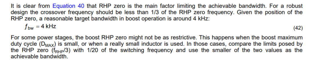
- How should I set my crossover frequency(The data sheet and the calculation tool indicate different values)? What will it affect my system?

- Which parameters are related to efficiency and stability, and how should I improve (I know the crossover frequency, ESR, compensation device will affect, but what is their relationship? I hope to understand)
thanks
BR
jeson