This thread has been locked.

If you have a related question, please click the "Ask a related question" button in the top right corner. The newly created question will be automatically linked to this question.

TPS51220A: DCAP Mode Jitter measurement

Part Number: TPS51220A
Other Parts Discussed in Thread: TPS51220

Hi Experts, 

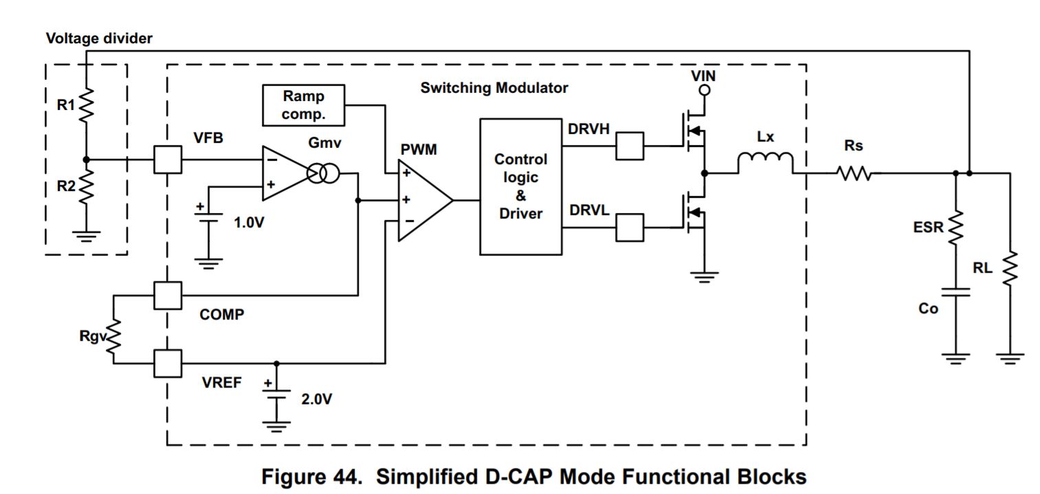
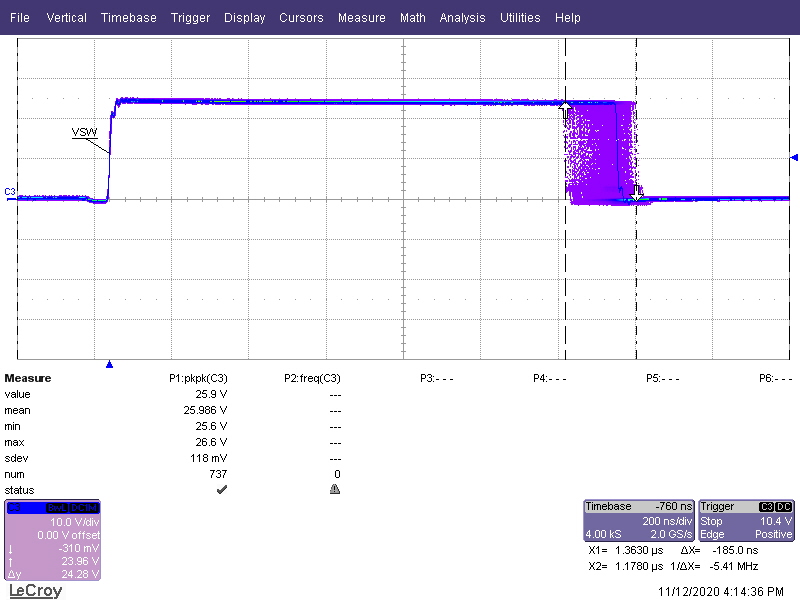
About the Jitter of DCAP, I use TPS51220 to build 24V to 5V  and 24V to 12V.

The jitter of 12V rail is around 290nS, the other channel, 5V, is around 165nS, Rcomp is 10K for both.

Lower the resistance could improve the jitter time, but for 5V, it need to parallel a 47pF with Rcomp = 7.86K.

Is it a correct way to improve jitter?

Or jitter is not a critical issue for DCAP mode converter ?

Thanks.

  • Hi Alan,

    Your understanding is correct. In D-CAP mode, the ramp comp is for reducing jitter. For the way it works, you can refer to the picture that I upload.

    In the block diagram, it can be seen that the Rcomp in D-CAP mode determines the gain of feedback inside the controller. With smaller Rcomp, the fb gain become smaller. And that increases the proportion of the ramp components in the comparator. Thus the jitter performance can get better with smaller Rcomp.

    I'm sorry that I didn't understand your meaning for adding parallel 47pF. Could you give some explanation?

    Regards,

    Andrew

  • Hi Andrew, 

    This is my Vsw waveform, I'm very confused, it looks not DCAP mode jitter. 

    Bus for my controller setting, it set as DCAP mode.

    TPS51220.pdf

  • Hi Alan,

    First, jitter does not represent small signal instability. In fact, jittering is a normal action of control loop against timing deviation caused by any accidental event such as noise, or the blanking time, adjusting back to the regulation point. A small amount of jittering does not harm the voltage regulation. For D-CAP mode control, since it's a hysteresis control and the time to start next switching period is determined by the time when VFB=Vref, so some noise on FB will have influence and causes the jitter.

    For the methods to reduce the jitter, I want to check that if the waveform is tested with 10kohm "Rcomp"? If yes, you can solder down the parallel cap and change the resistance to 6kohm. Also can you capture and share the waveform on FB pin? Too small ripple on FB pin will cause large jitter. 

    Thanks.

    Andrew

  • Hi Alan,

    Since there's no new reply from your side, I will click "TI thinks resolved" and close it.

    You can send me email to "andrew-xiong@ti.com" if there's more items to discuss.

    Regards,

    Andrew