This thread has been locked.

If you have a related question, please click the "Ask a related question" button in the top right corner. The newly created question will be automatically linked to this question.

TPS65218D0: PMIC cannot work well if VCC_5V_PMIC power is dropped down and then recovered.

Part Number: TPS65218D0
Other Parts Discussed in Thread: TPS65218

Hi

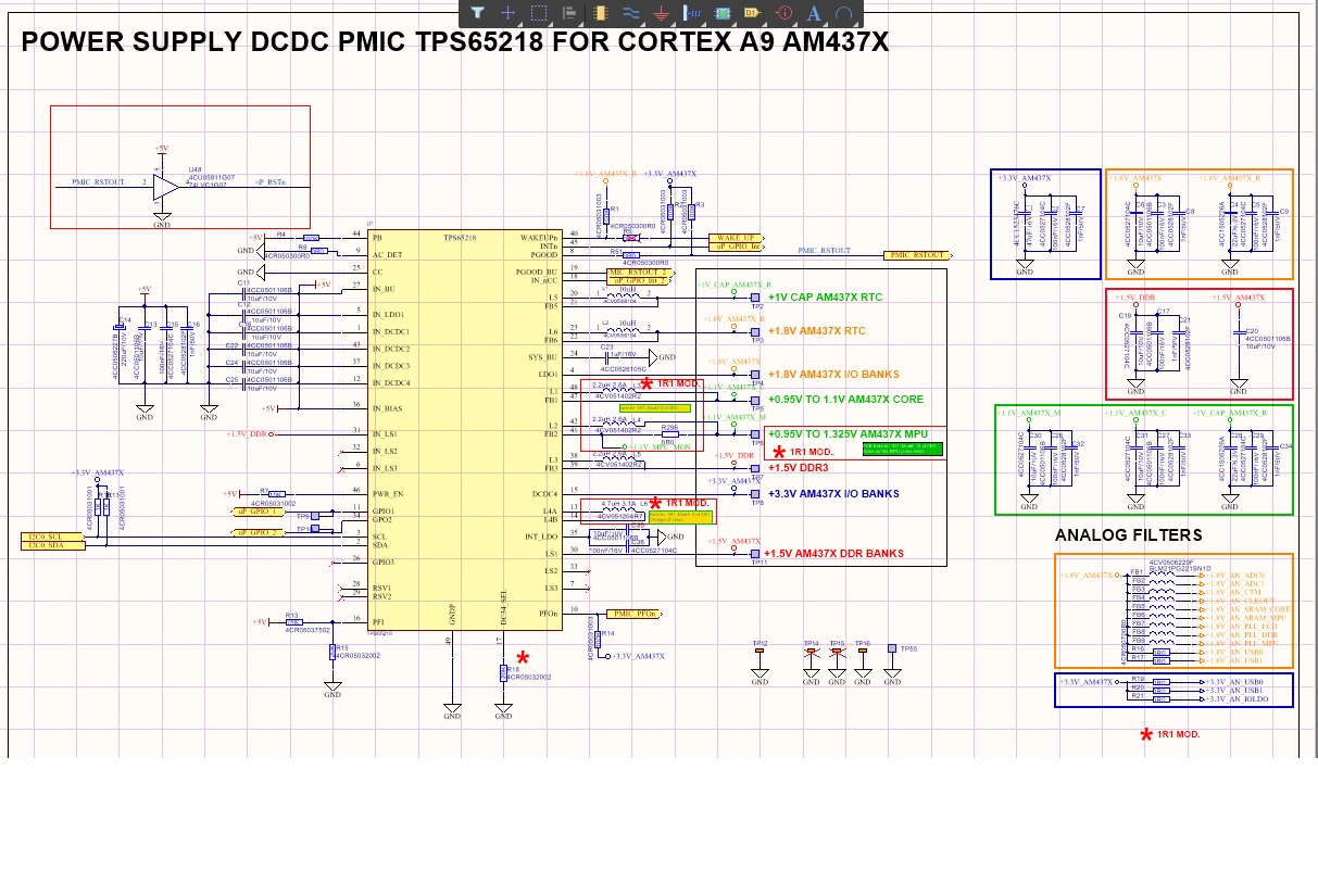
I have a design with TPS65218. I´m making tests for changing this component for the new recommended reference TPS65218D0, but I have found a problem.

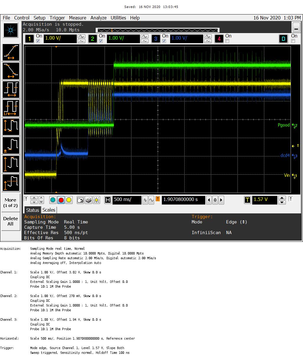
When I have little dips in power supply or make a star-up ramp in power supply (EN 61000-4-11)  the Am437x microprocessor doesn´t start. But with the previsious reference, without D0, I don´t have any problem.

For example, if we power up in steps , for example, 0.4 v, many times the PMIC doesn´t start correctly. But the oldest reference, without D0, works good.

The schematic is :

  • Dina,

    The picture did not get attached properly. Can you use the Insert/Edit Media button, which looks like a Polaroid photo with a little plus sign '+' in the bottom right corner?

    It is possible you are having an issue due to the STRICT bit, which measures for over-voltage AND under-voltage on the TPS65218D0 (STRICT= 1b).

    Can you measure the input voltage (VIN), DCDC4 output, and PGOOD signal to see if PGOOD ever goes high? If not, I expect it is because DCDC4 does not ramp up to the expected voltage within the correct timing during start-up.

  • Vin has an strange waveform because the power supply is starting with step ups. Remember that the problema appears with this type of starting. During a time the power supply doesn´t work properly

  • The problem, in my opinion, is that you are using DCDC5/6 but you have CC pin connected to GND.

    If you are using DCDC5/6, then there should be an evenly-matched resistor divider from VIN (5V) to CC (R1 = R2 = 10k). Then you need to "break the factory seal" by setting FSEAL=1b according to the datasheet. Personally, I disagree with the wiring in section 6.1.1 Applications Without Backup Battery of the datasheet and I think it is the cause of your issue. Power supplies that are hovering around multiple UVLO thresholds during a "brownout" always seem to cause issues in my experience. Connecting a "fake" battery to the CC pin allows the part to transition over to the backup supply as it was intended to do and then return to normal operation when the power supply stabilizes.

    If you are not using DCDC5/6, the whole subsystem should be terminated according to the datasheet in 6.1.2 Applications Without Battery Backup Supplies which is a reliable solution. In this case, you would use an alternate wiring for powering the RTC domain with LDO1 as shown below:

    Or you could disable the RTC system of the processor completely.

  • I have done the test and the problem persists.

    The strange thing is that with the TPS65218 component it works for me.

    I just wanted to test the new component to have the option to place either one

    Somehow TPS65218  seems "less sensitive" to this transient power supply misbehavior. I don't know if this can be of help

  • Thanks for the update. I will need to test for myself and see if I can identify a root cause.

    For now, you can continue to use TPS65218 device. It is NRND but we have no plan on changing this device to EOL status.