This thread has been locked.

If you have a related question, please click the "Ask a related question" button in the top right corner. The newly created question will be automatically linked to this question.

TPS61030: Enable pin disabling loads too early??

Part Number: TPS61030
Other Parts Discussed in Thread: TPS3700EVM-114, , TPS63010

Hello,

I have designed a boost converter with the use of a TPS61030 which leads to a 1 A USB load. This converter is preceded by a voltage comparator similar to the TPS3700EVM-114 with a change in the R1 R2 voltage divider for INA+ found in the schematic below:

My comparator is triggering the enable to low at 3.25 V whenever there is no load but when there is a load, the enable is triggered as early as 3.37 V. The diagnosis of the voltage on the enable pin is mentioned towards the end of the thread found here:  

Is there a way to ensure that the enable pin only triggers once it hits the preset falling threshold of 3.25 V when the load is introduced??

Thanks,

Ibrahim


  • Hi Ibrahim,

    From my understanding, the issue is when there is no load of TPS63010, the battery voltage falls to 3.25V to disable TPS63010 while the battery voltage falls to 3.37V to disable TPS63010 when there is load, right?

    I wonder which point do you test VBat and how the battery is connected to your board. Is it tested on the EVM, in other words, between R37 to PGND? If your battery is connected with a long cable and you test the voltage on your battery, the voltage drop on cable would be ignored. When a load is added, the real VBat will be lower that battery voltage.

    Best Regards,

    Yichen Xu 

  • Hello Yichen,

    Yes that is primarily the issue. I am in fact testing it with the EVM where the positive lead is VBAT and the negative lead is PGND. These voltages were the voltages shown on my lab bench power supply when I do or do not connect a 1A load to my TPS61030. I have noticed that the voltage on the board's OUTA (connected to the EN pin) is 2.7 V when its logic HIGH and around 2.3V when its logic LOW.  These measurements were with a digital multimeter since I do not have access to an oscilloscope due to covid procedures.

    Is there a reason why my comparator is triggering OUTA to be a lower voltage when the voltage being supplied is around 3.35 V?? Could it be the voltage drop at the supply due to the addition of the load??

    Thanks,

    Abe 

  • Hi Abe,

    There is a voltage drop on the cable between the power supply and the EVM. When adding 1A load the voltage drop will be obvious. So you can not trust the voltages shown on your lab bench power supply because the real voltage between VBAT and PGND will be lower. Please also use digital multimeter to measure the voltage between VBAT and PGND. You may find when there is a load, the the voltage between VBAT and PGND is 3.25V while the voltage shown on power supply is 3.37V.

    Best Regards,

    Yichen 

  • Hello Yichen,

    That's exactly what's happening and my current pulled is greatly reduced from 1.13A to 0.3 A between 3.8V and 3.6V respectively. How can I bypass this?? Would using a push pull comparator topology work better for my application?

    Thanks,

    Ibrahim

  • I have also noticed that when I introduce the load to the boost converter when the power supply is at 3.7V my VBat input is 3.5V but my 5V output is 1.14V. Removing the comparator OUTA net with the Enable pin would return the regulator to function normally without these strange changes in voltage values.

  • Hi Ibrahim,

    In your real application, I suggest that you put battery near to TPS61030 and make sure the trace connecting them is wide enough. So the resistance between battery and TPS61030 is very small and the voltage drop on it is ignorable. So only triggering 3.25V with light or heavy load will not be a problem. If you want test this on EVM, make the cable as short and thick as possible to minimize the resistance. And since there is 0.2V voltage drop on your cable, the load you introduced must be too high so the TPS61030 or your power supply reaches current limit.

    Best Regards,

    Yichen 

  • Hello Yichen,

    As per my last post, the enable pin seems to be the trigger that sets the output voltage and current to be very low. My VBat input on my comparator EVM when there is a load is 3.5V and should not be triggering the comparator to send a false logic low signal to OUTA or the enable pin, yet the enable pin reads it as such and greatly limits the voltage and current supplied. Regular load operation is carried out only when supplying from a 4 V> power source and I require it to provide this load operation from 3.3 - 4.2V.

    Can I use a push pull comparator instead??

    Should I use a 10uF capacitor at the input to minimize voltage drop??

    My load is 1 A and is not exceeding that according to my multimeter. It provides 1 A just fine between voltages of 2.8 to 4.2V when it is not connected to the comparator. When connecting a lab test bench power supply, I am not able to drive my device properly.

    Hence why I think the enable pin isnt triggering completely low at 3.7 V since there is still a signal being monitored at the output. This signal is just very low.

    Best regards,

    Abe

  • Hi Abe,

    The voltage drop is caused by parasitic resistance of your cable so adding input capacitance will not help.

    I do not think the type of comparator will affect. Since the voltage triggering value is changed, there may be some damage on your board. Please capture the waveform when the false triggering happens, it should contains VBat, EN, and current of inductor. Of course, replace the comparator with a new one first to avoid damage issue is better.

    Best Regards,

    Yichen

  • Hello Yichen,

    As I mentioned in the earlier replies: "I do not have access to an oscilloscope due to covid procedures."  Is there any possible fix other than changing the cable width and length to fix my problem?? Would lowering my Vlow threshold fix this?? Should I spec a different comparator with an internal reference closer to my target voltage?? 

    Would the change in the internal reference of my comparator improve my performance since I am opting for a voltage divider that does not limit my voltage as much as it is now with my current design??

    Thanks,

    Abe

  • Hi Abe,

    You mentioned you are using our EVM for testing in the other E2E link you attached. My advice of changing the cable width and length is for your product board in  the future. I suppose the battery and our devices are all on the same one board. This is to make sure the triggering happens at your desired battery voltage. 

    The issue you are facing is that the triggering voltage of comparator is not the value you set, and the Boost converter can work well alone, right? The triggering should happen when VBat =3.25V only. VBat is the real source voltage on your EVM not the power supply voltage. So please use multimeter to check if the VINA+ is 394.5 mV when triggering. The schematic you designed should work fine if there is nothing damaged whatever the load is unless exceeding current limit. Please check if the comparator works well, or you can change a new one(NOT another kind of comparator). I can not give you advice on choosing comparator because I only support Boost converter.

    Best Regards,

    Yichen Xu 

  • Hello Yichen,

    Luckily I have ordered 3 spare TPS3700EVM-114 boards for testing and I tried using a different board for the sake of comparison. I did a test on the new one to ensure the previous board was not damaged. 

    My initial battery voltage before adding the 1 A load was 3.89V with VINA+ = 0.47V. After adding the load, the voltage went down to 3.4V with VINA+ = 0.399V. So I doubt there was damage on the board, it may be the configuration or resistor divider limiting the voltage being monitored which is making the board reach its threshold earlier than expected. For instance, if I keep draining the battery the way I am, the comparator would trigger the converter's enable pin within 30-45 mins max before the actual capacity reaches the capacity the 3.2V threshold is mapped to. This gives me 50% or even 45% or less of the capacity of the battery to work with. One other solution is increasing the capacity of the battery but that might not be the best course of action since the battery is being charged by a solar powered source and it is very intermittent. Is there an obvious design mistake or is there a viable solution I can work towards to give me longer discharge times that would disable the battery at 3.2 V?

    Thanks for your help,

    Abe

  • Hi Abe,

    Let divide the concept VBat and battery voltage first. VBat is the actual supply voltage on your EVM. Battery voltage is the power supply(a real battery or a voltage source) voltage connected to VBat by a cable. If VBat is your so called battery voltage, 3.89V-0.47v or 3.4V-0.399V are normal, which are consistent with the resistor divider. Back to the first question, there is a voltage drop between battery voltage and VBat because there is parasitic resistance on your cable. This is why VBat changes to 3.4V from 3.89V when adding 1A load. You need to regard VBat as your practical battery voltage because as I suggested last reply, when you design your product PCB, you need to make sure the resistance from your battery to VBat as small as possible by placing them near and using wide trace or pour. So the battery voltage and VBat will be almost the same. And when VINA+ is about 394.5 mV and triggering enable pin the VBat will be 3.2V, as well as your real battery voltage. Hope this will solve your issue.

    Best Regards,

    Yichen Xu 

  • Hello Yichen,

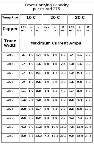
    Can I expect a better performance from my design when setting a pcb for trace widths of 0.1 inches for the main VBat power net?? Also I cant help but wonder whether my RT is really low and what could be a cause of concern?? I noticed a thread here for the same device with an excel tool:  

    The designer of the tool mentioned that the RT value should be upwards of 1Mohm. I have attached my version of the excel tool below.Copy of Supervisor Resistor Calc for TPS3700 and TPS3701 .zip

    Thanks for your help so far,

    Ibrahim

  • Hi Abe,

    According to your working condition, 0.1inch should be enough. Please refer the table below. And this table is focused on temp rise, and we want small resistance. So please make the trace as short as possible. 

    About Rt, the larger the Rt, the less the power consumption but less accuracy. "For sanity check, take your monitored rail voltage and divide by RT and make sure this is at least 100x larger than 25nA + 15 nA. (25nA comes from the MAX I_INA+ current in table 6.5 and 15nA comes from I_INB-.)" And your Rt has 4.6uA current with 3.2V VBat. This is enough for the comparator. If you don't use comparator B the trace connecting INB- could be removed.

    Best Regards,

    Yichen Xu 

  • Yichen,

    Fantastic, this is great! I am moving to a larger capacity battery for this system and the company went ahead and purchased an oscilloscope for me to use. I will provide any updates or screenshots that may be useful.

    Best regards,

    Abe

  • Hi Abe,

    Hope to hear good news from you! If there are any new updates welcome to start a new question.

    Best Regards,

    Yichen