This thread has been locked.

If you have a related question, please click the "Ask a related question" button in the top right corner. The newly created question will be automatically linked to this question.

UCC256302: Gate no switching until FB > 5V in burst mode

Part Number: UCC256302

Hi, 

I'm testing this device under no-load conditions with the schematic diagram shown below.
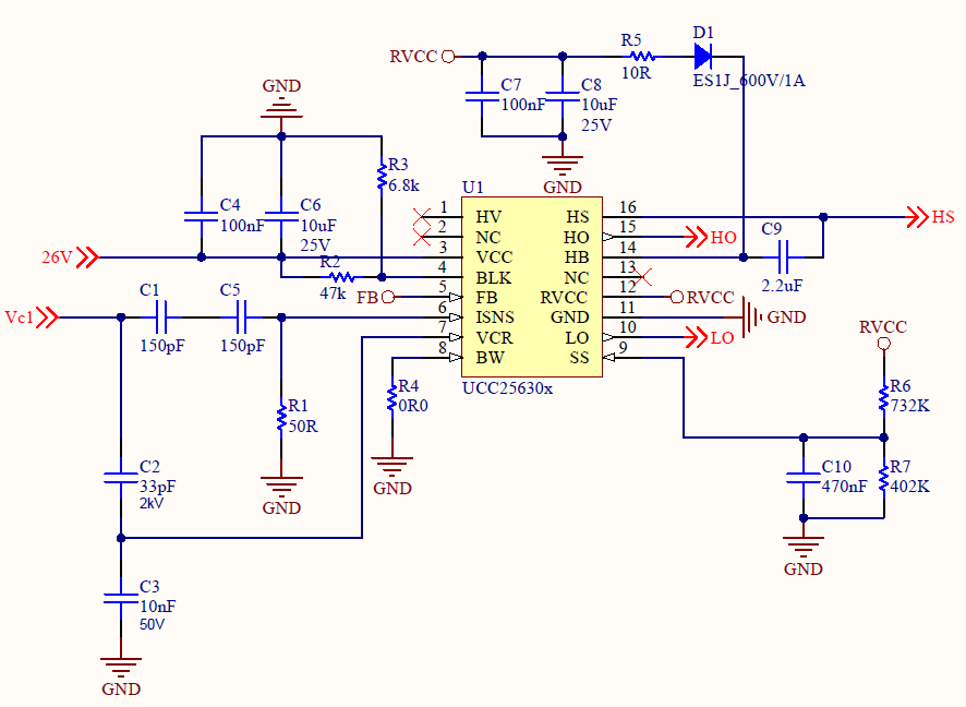
 (Fig. 1)

Other setups in Fig. 1 are:

- VCC is supplied externally.

- Vin UVP/ OVP is not used so BLK is tied to VCC thru a volt divider, which results in 3.3V at BLK.

- Vo UVP/ OVP is also not used so BW is short to ground. 

- The LL/SS resistors and BLK voltage set the burst mode threshold (VLL) around 0.9V.

From the startup, the gate starts switching as expected, although the termination of soft-start seems a bit early. 
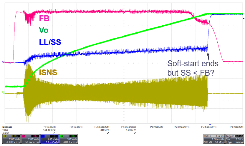
 (Fig. 2)

The condition of soft-start termination should be SS > FB.

However, according to Fig. 2, SS goes to BLK (3.3V), which indicates the end of soft-start, but FB is still around 5V. 

And then it enters burst mode as there is no load at the output:
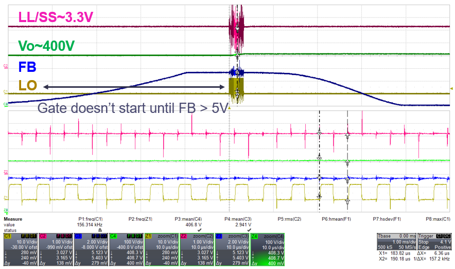
 (Fig. 3)

As Fig. 3 shows, in burst mode, FB ramps up from zero but there is no gating signal until FB> 5V.

The optocoupler may experience saturation but LO does not start when FB > VLL (0.9V). 

I also ever tried to open the feedback loop and supply FB externally. LO starts when FB > ~5V and stops when FB is less than the same voltage,
which is aligned with the closed-loop test results but not desirable. So I'm wondering what is wrong with the configuration. 

In summary, I'm wondering why
1). LO stops before FB drops below SS at the end of soft-start?
2). LO doesn't start switching when FB> VLL in bust mode?


Regards,
Daniel

  • Hi Daniel,

    An expert will get back to you soon !

  • Hi Daniel,

    The FB signal is the amount of current that is pulled out of the FB pin, the FB signal is not the FB pin voltage itself. To monitor the FB signal, you need to measure the current pulled out of the FB pin. This is why LO stops before FB pin voltage drops below SS and also why LO doesn't start switching again when FB pin voltage is >VLL.

    Best Regards,

    Ben Lough

  • Hi Ben, 

    Thank you very much for your prompt reply. 

    It is interesting to know that the FB signal is not the FB pin voltage itself.

    According to the datasheet block diagram (Fig. 4), during normal operation, the FB PMOS is always on; so my understanding is that the FB signal should be equal or closed to FBreplica, that is, FB = FBreplica = (I_FB - I_opto) x RFB. The FBreplica is basically Vcomp that feeds to the HHC controller in closed-loop regulation.

    But as you pointed out that FB signal is not the FB pin voltage, would you please suggest the correct equation? Or if I managed to measure the current pulled out of the FB pin (I_opto), how does I_opto eventually convert to Vcomp that feeds into HHC? 

     (Fig. 4)

    Kind Regards,
    Daniel

  • Hi Daniel,

    You are correct. FBreplica is equal to (IFB-Iopto)*RFB. During normal operation, FBreplica is the same as Vcomp.

    Best Regards,

    Ben Lough

  • Hi Ben, 

    Thank you for clarifying this point.

    In Fig. 3, I'm still wondering why LO does not start switching until FB > 5V but not VLL, if FB is the same FBreplica in this condition?

    Kind Regards,
    Daniel

  • Hi Daniel,

    The LLC controller attempts to loosely regulate the FB pin voltage to around 5V. This is done to provide better transient response and avoid some of the delays associated with the opto-coupler being saturated. When the current pulled out of the FB pin is within 0uA to 82uA, the FB pin voltage will be around 5V. When the opto-coupler pulls more current than the FB pin can support, the controller will allow the FB pin voltage to collapse to 0V. 

    Best Regards,

    Ben Lough

  • Hi Ben, 

    Thank you. I think that makes more sense to me now. 

    So in normal operation, can I describe the feedback chain here as FBreplica = (IFB - I_opto) x K x RFB, 
    where K might represent an internal current mirror gain that is probably equal to 1?

    After that, FBreplica / 2 + 3 = VTH that compares with VCR if I understand correctly.

    Cheers,
    Daniel

  • Hi Daniel,

    It is not an internal current mirror but yes, the relationship is FBreplica = (IFB - I_opto) x RFB.

    Yes, VTH is equal to FBreplica / 2 + 3.

    Best Regards,

    Ben Logh

  • Hi Ben,

    Thank you very much for your explanation. 
    That clarifies my issue.

    Cheers,
    Daniel