This thread has been locked.

If you have a related question, please click the "Ask a related question" button in the top right corner. The newly created question will be automatically linked to this question.

UCD9090A: PWM frequency configuration

Part Number: UCD9090A
Other Parts Discussed in Thread: UCD9090,

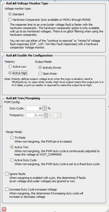
Two pins of the UCD9090 are PWM pins (pins 22 and 23) which I want to use for margining/trimming (all FPWM pins are already in use for other supplies). In the Fusion Digital power designer under hardware configuration it is possible to configure the duty cycle but not the frequency, this is grayed out (see attached picture). How can I configure the frequency and set it to for example 28204 Hz? It is now only 980 Hz. I have attached the window of Fusion for configuring the margining. Configuring the frequency for the FPWM pins no problem, the frequency is not grayed and can be set to, in my case, to 7.272727MHz.

Thanks for any suggestions, Robert.

  • Hello

     As mentioned in the data sheet 7.4.14.2,  the frequencies of PWM1/PWM2 are fixed at 10K and 1K Hz respectively. They can not be changed.

    Do you want to margin more than 8 rails? if that's the case, you may consider other UCD device?

    Regards

    Yihe

  • Hi Yihe,

    Thanks for your reply. Yes, I have seen in the datasheet that the PWM1 and PWM2 frequencies are fixed. In an other project we use the same sequencer. Strange enough here are the frequencies for PWM1 and PWM2 set to 28.409kHz (but also grayed out). See picture below. Because this programming of the sequencer was made several years ago I can not recall anymore how we managed this. Is there maybe a main clock frequency which I can set what makes this higher PWM frequency at the end?

    Thanks for your support,

    Robert.

  • Hello

    Could you share the project file with 28KHz setting?

    Have you measured the output of PWM1/2 to see what the real frequencies are?

    The main clock frequency is fixed.

    Regards

    Yihe

  • Hi Yihe,

    Attached the project file. Also attached a measurement done on a scoop for PWM1. PWM2 has the same output.

    Best regards,

    Robert.

    FS422_FS3422_Gen4_UCD9090.xml

  • Hello

    Thank you very much for the project file and waveform. It is a mistake of the data sheet.

    For both UCD9090 and UCD9090A, PWM1 and PWM2 frequencies can be 1Hz to 7.8125 MHz.

    We will update both GUI and data sheet to address this issue.

    There is a workaround that you can set the frequency of PWM1 and PWM2.

    Please refer section 10.17 and 10.18 of https://www.ti.com/lit/ug/slvu352g/slvu352g.pdf

    Basically, you have to use the low level PMBus command to configure the frequency to bypass the limitation from top level GUI.

    section 10.17 is the command(0xE0) to select which PWM pin, for PWM1 pin, the payload of command(0xE0) is 0x08, and it is 0x09 for PWM2

    section 10.18 is the command(0xE1) to set the frequency and duty cycle.

    Here is a training video about how to use GUI's low level I2C debug

    https://training.ti.com/fusion-power-designer-low-level-i2c-smbus-debugger?context=1136655-1139495-1136567

    If you have the target frequency and duty cycle for both PWM1 and PMW2, I can help modify your project file so that you do not have to do this yourself since it is our mistake.

    Regards

    Yihe

  • Hi Yihe,

    Many thanks for your great support. This helped a lot.

    I have attached the project which I want to have modified to the right target frequency and duty cycle for PWM1 and PWM2.

    The frequency needs to be set to 18,409kHz and the duty cycle is 18% (see the picture in one of my previous replies). Also the 'Margin mode' must be set to 'Active trim'.

    I was able to modify the settings for PWM1 and PWM2 with the low level PMBus command tool. PWM1 is working now but PWM2 behaviors differently. If I program it exactly the same as for PWM1 I don't see a PWM output but a DC signal at about 3.2V. If I you could modify the project file I hope it will work as expected.

    Best regards,

    Robert. 

    FT4x24bT_UCD9090.xml

  • Hello

    Please see the project file attached. I had changed the frequency to 18.407KHz.

    FT4x24bT_UCD9090 - TI.xml

    Regards

    Yihe

  • Hi Yihe,

    I had to modify your project file a little bit to get the right values I wanted to have. For PWM1 and PWM2 the frequency is set now to 28.409kHz and the margin mode is set to 'Active trim'. I have attached the modified project file. Changing the frequency was done by writing to 0xE1 : 0xDA4000006EF90000 for the pin ID's 0x08 and 0x09.

    Hopefully the new datasheet and updated Fusion tool will be released soon.

    Best regards,

    Robert.

    FT4x24bT_UCD9090 - TI - RV.xml

  • Hi Robert

    Thank you for reporting this. Please subscribe the Fusion GUI Alert to get the notification about new GUI release.

    https://www.ti.com/tool/FUSION_DIGITAL_POWER_DESIGNER

    Regards

    Yihe