This thread has been locked.

If you have a related question, please click the "Ask a related question" button in the top right corner. The newly created question will be automatically linked to this question.

LP5012: Repeating the INITIALIZATION command

Part Number: LP5012

Hi support team,

LP5012RUKR is used by incorporating it in the sub board.
If the power supply is stopped due to poor contact with the main board, I think that communication will not resume unless it is restored by the sequence shown in the figure below.

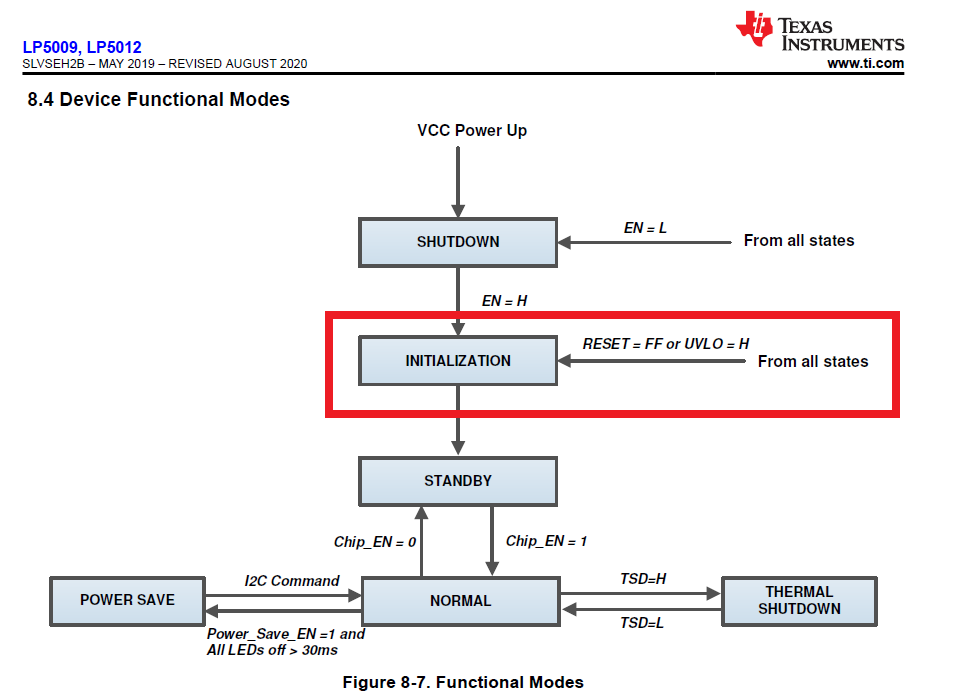
However, since there is no mechanism to determine the necessity / unnecessity of initial communication between the main and sub boards, there is a problem that the LED does not light once a contact failure occurs.

On the main board side where the microcomputer is located, it is not possible to determine whether a communication failure with the LED driver has occurred.
Therefore, when I set the OUTx_COLOR register while continuing to send INITIALIZATION at a cycle of 0.1ms, it seems that it is working without any problem.

So I have questions.

(1)
If the command is sent in the order of INITIALIZATION → OUTx_COLOR setting → INITIALIZATION, is there any change in the internal state of the LED driver?
Apparently, INITIALIZATION (LED not lit) → OUTx_COLOR setting (LED lit) → INITIALIZATION (LED lit)
It looks like there is no problem.

(2)
If I send commands in the order of INITIALIZATION → OUTx_COLOR setting → INITIALIZATION and there is a change in the internal state of the LED driver, are there any concerns to assume?
At first glance, there seems to be no problem, but I am worried that the current consumption will increase or the LED will turn off without permission.

(3)
Are there any concerns if the INITIALIZATION command is repeatedly sent, such as with a 0.1ms cycle?

I think it is unexpected that the INITIALIZATION command is sent repeatedly, but if there is no problem, I would like to consider sending it repeatedly.

Regards,
Dice-K

  • Hi Dice-K,

    It seems to be OK. I will check it on the lab and replay to you late. 

    Best Regard

    Monet Xu

  • Hi Monet,
    Thank you for your support.

    I look forward to your confirmation in the lab.

    Best regards,
    Dice-K

  • Hi Monet,

    When will the result of the lab come out?

    Best regards,
    Dice-K

  • Hi Dice-K,

    I did some test on the LP5012 EVM and it can be working normally. When you select this program, please take care of that after each INITIALIZATION you need to configure  the related registers correctly.

    and when the power supply is stopped due to poor contact with the main board, the MCU will receive an interrupt.

    Best Regard

    Monet Xu

  • Hi Monet,
    Thank you for your support.

    I have two questions about your comment.

    (1)
    "please take care of that after each INITIALIZATION you need to configure the related registers correctly."
    What kind of processing is required specifically after INITIALIZATION?

    (2)
    "when the power supply is stopped due to poor contact with the main board, the MCU will receive an interrupt."
    What kind of route does the MCU receive an interrupt?


    Best regards,
    Dice-K

  • Hi Dice-K:

    (1)
    "please take care of that after each INITIALIZATION you need to configure the related registers correctly."
    What kind of processing is required specifically after INITIALIZATION?

    Such as 'DEVICE_CONFIG0','DEVICE_CONFIG1','LED_CONFIG0',al etc. after INITIALIZATION, all registers will be set to the default data so you need to set the necessary register.

    (2)
    "when the power supply is stopped due to poor contact with the main board, the MCU will receive an interrupt."
    What kind of route does the MCU receive an interrupt?

    it depends to what kind of MCU do you use. and the reference interrupt FLAG will storage the status.


    Best regards,
    Monet Xu