Other Parts Discussed in Thread: LM5146-Q1, LM5164
Hi there,
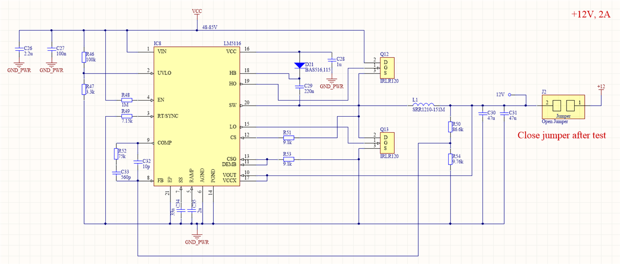
I'm currently designing an LM5116 based DC-DC converter that outputs 12V, with an input voltage range of 48V - 85V (Fsw=400kHz). The DC-DC converter in this application has a typical load current of 1A (designed for a current rating of 2A however).
I have a few questions regarding my component selection for this design and it's thermal performance.
The converter is part of a small inverter PCB, and the available space for copper planes is limited. I've maximized the area of the copper planes as much as possible, but the LM5116 IC and the MOSFETs are still reaching ~80°C at Vin=85V, Vout=12V, Io=1A (no airflow).
As this is my first attempt at designing an LM5116 based DC-DC converter, do you have any tips and tricks I could try to reduce the temperature of the devices.
Any advice or general improvements on my component selection and component values would also be greatly appreciated.
I calculated most of the component values using the equations from the LM5116 datasheet, with some inspiration from a WEBENCH design.
One area of the design I would like some guidance on is the value of the inductor. As per the datasheet, I used to minimum load current to calculate the minimum value of the inductor, however, the minimum load current on this design is approximately 100mA (just the MCU and some logic being powered), hence I selected a 150uH inductor. Other reference designs I have seen as well as the WEBENCH designs use much lower value inductors, such as 10 or 33uH. Would it be suitable to use a much lower value inductance, what would the effect on the output voltage waveform be?
I've attached a folder that contains the schematic, bill of material, images of each copper layer, scope shots, thermal images and a spreadsheet that I made to calculate component values using the datasheet equations.
Any advice for improvements would be welcome!
Many thanks,
Ben


