


Other Parts Discussed in Thread: TPS566335
Hi Team,
Our customer is using TPS566335 for their TV SoC Vcore power supply, and using remote feedback sensing method to connect the feedback resistor divider with a 47pF feedforward capacitor. During their board test, they found that when the feedforward capacitor Cff is placed in different location, it will have different influence for the Vout voltage, summary as below:
1. Cff connected directly in parallel with upper feedback resistor:
The problem for this connection is it will influence the Vout voltage from normal 1V to around 0.7V in worse case on customer's board.
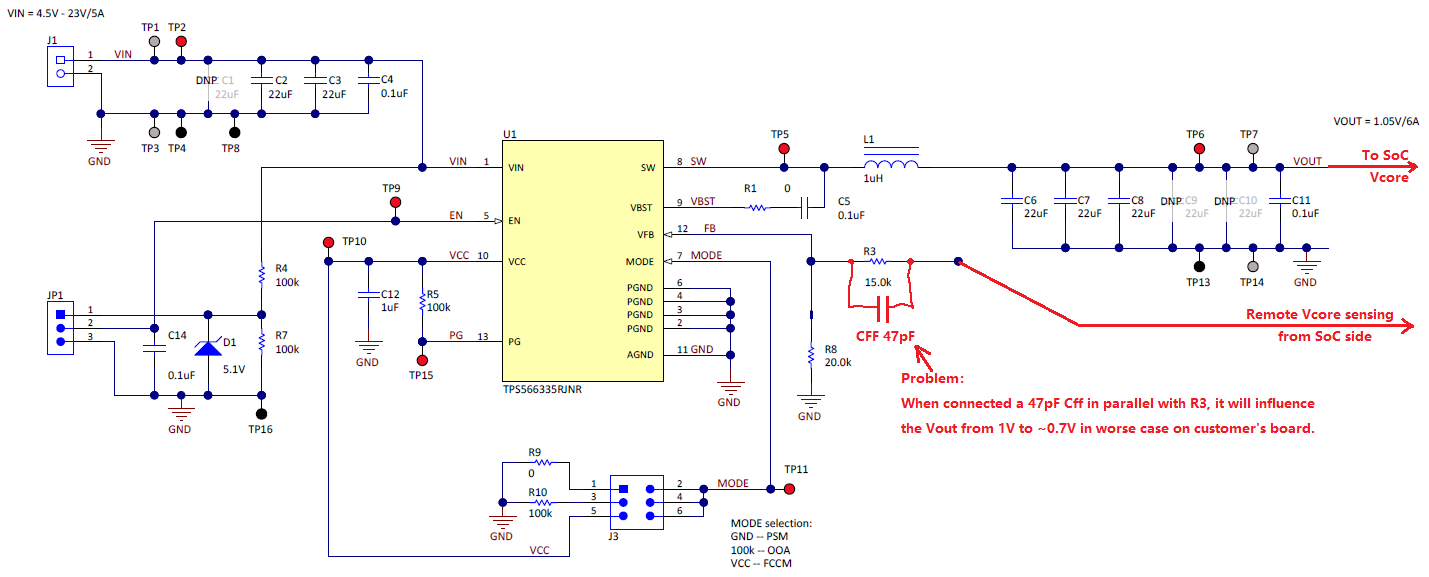
2. Cff connected as below between FB pin and near end output capacitors:
There is no influence for the Vout voltage and even better for output ripple and noise compared with disconnected.

So our question is, which CFF connection method is preferred in our design? Per our understanding, the 1st type should be more reasonable, but not sure why it will influence the Vout voltage. Can you help to simulate and analysis for these two connection types and give us some explanations?
Thanks a lot!

