A related question is a question created from another question. When the related question is created, it will be automatically linked to the original question.
If you have a related question, please click the "Ask a related question" button in the top right corner. The newly created question will be automatically linked to this question.
We do recommend the Cf capacitors commonly be 10uF, CBQ53, CBQ45, CBQ41.
CBQ51, CBQ25, CBQ26 are not normally used, these signals are filtered by the other caps on these signals (CBQ38, CBQ37, etc)
The 1uF Cc capacitors will show some voltage errors during balancing due to settling time, many designs use a smaller value such as 0.47 or 0.22 uF
BQ76940 ALERT pin (ALARM) can be sensitive to noise. Many designs will include a small capacitor near the pin, across RBQ67. Time constant should be less than 250 us. 470 pF is common with the 499k.
The cell input limit zeners VBQ1, VBQ2, VBQ6... should be at least 1.5x the cell voltage if balancing every 3rd cell or 2x the cell voltage if balancing every other cell. The VCn inputs pull together during cell balancing, the adjacent cell input voltage must be allowed to increase.
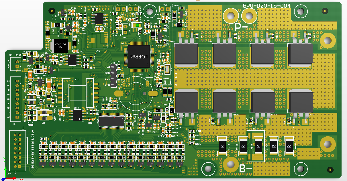
On the PCB
Be sure the balance resistors can handle the power for the intended cell voltages (RBQ79, RBQ71, RBQ66...)
You want a signal traveling from the cell input to reach the filter components before the IC, it seems the network does that. Also check for the Cf power filter caps which are harder to route. Check for possible crosstalk past the filter (BATn to VCm) if the traces interleave or are on adjacent layers.