This thread has been locked.

If you have a related question, please click the "Ask a related question" button in the top right corner. The newly created question will be automatically linked to this question.

UCC27714: SN6505B dedicated high side driver

Part Number: UCC27714
Other Parts Discussed in Thread: SN6505B,

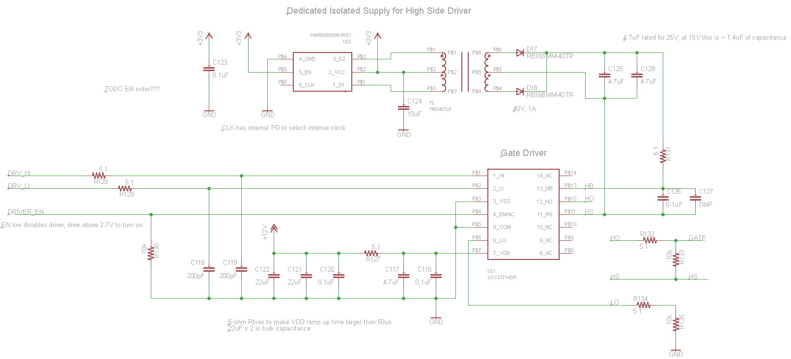
Please review the schematic below. 

Any issues with the SN6505B powering the high side supply? 

Is the SN6505B output voltage set properly?

Should the SN6505B be enabled before the UCC27714 driver?

Any issues with only using the high side of UCC27714 in this configuration?

  • Hello Spencer,

    Thank you for the interest in the UCC27714. There should be no issues with the SN6505B providing the HB bias, this is the suggested solution if long on times of the high side driver is required, or if bootstrap bias is not practical for other reasons.

    For the output voltage setting, this is very dependent on the transformer turns ratio, I looked for the part number shown on the schematic for T2 and did not get any search results (correct). Confirm the transformer turns ratio required in the SN6505 datasheet. There are magnetic vendors such as Coilcraft and Wurth who make off the shelf transformers for the SN650x devices.

    For the question on should the SN6505B be enabled before the UCC27714. I would suggest a power sequence of provide VDD for the UCC27714, ramp bias for the SN6505B, enable the UCC27714, start PWM to the UCC27714.

    The UCC27714 can be used as a high side driver only, the LO and HO are independent drive channels that respond only to the LI and HI inputs, and enable function. I see there is a connection to LI and LO has resistors to ground. Is there any intention to switch the LO output, and what would be the reason to switch LO. LI can just be tied to ground if not using the LO output.

    Confirm if this addresses your questions, or you can post additional questions on this thread.

    Regards,

  • Hi Richard, Thanks for the quick response!

    Transformer is Wurth 750343725, Mouser 710-750343725 and has a turns ratio of 1:3.9

    https://www.we-online.com/catalog/datasheet/750343725.pdf

    -> My understanding is with a 3.3V input this will provide a high enough voltage for the HB bias to be on for 100% or at least near 100% duty cycle. Do you see any reason this won't happen?

    Thanks for the power sequence, understood.

    No intention to switch the low side so I can add the LI to to ground connection.

    ->Does that mean that LO should also be pulled to ground or floating?

    Thanks,

    Spencer

  • Hello Spencer,

    Thank you for the turns ratio confirmation. The SN650x devices to work with a high duty cycle operation so the turns ratio should result in ~12-13V on the output. I think the SN650x datasheets have the guidance to confirm, and I see that the input to output is based on the transformer turns ratio in the SN6505 datasheet.

    If not using the LO driver I would recommend connecting LI to ground just to ensure the voltage level is 0 and reduce the risk of noise injection.

    Confirm if this addresses your questions, or you can post additional questions on this thread.

    Regards,