


RI have three questions about this IC. Can you answer to those?
- Why do you utilize boundary conduction mode (BCM) at heavy load? What is the merit to use BCM?
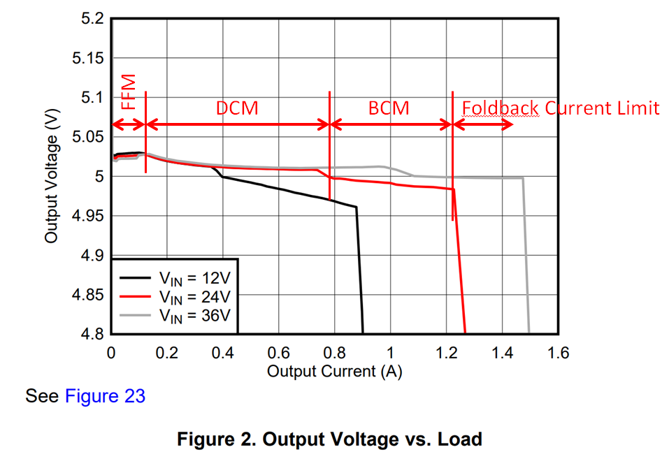
- In the figure below, is each range of current correct, such as FFM, DCM, BCM and current limit region?
- In the figure below, why does the output voltage go down by increasing the output current? Do you have any methods to calculate the output voltage drop?
Regards,
RYO
