This thread has been locked.

If you have a related question, please click the "Ask a related question" button in the top right corner. The newly created question will be automatically linked to this question.

LM3409-Q1: PWM dimming issue

Part Number: LM3409-Q1
Other Parts Discussed in Thread: LM3409

Dear team,

My customer tested PWM dimming in our EVM. They apply an external 30Hz PWM signal to our EN pin. But the customer found that PWM dimming can't work normally at first. When they remove C6 component, the PWM dimming works normally. But we don't understand why this cap has a impact to the PWM dimming. Could you please help analyze this issue?

When adding C6, the IADJ pin and LED+ waveform is as below,

IADJ,

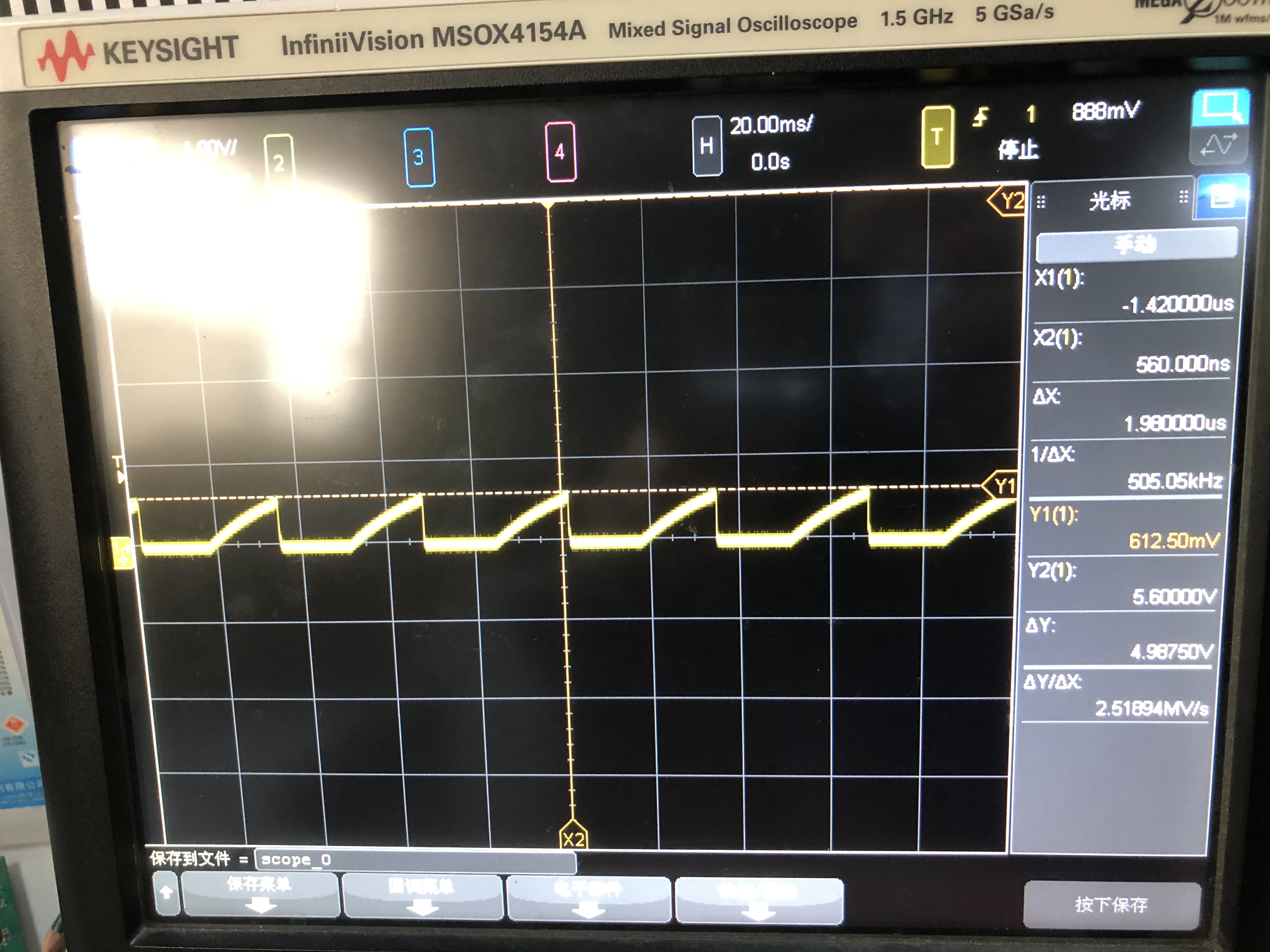
LED+, the pulse voltage should be 5V, but currently the voltage is only around 0.6V.

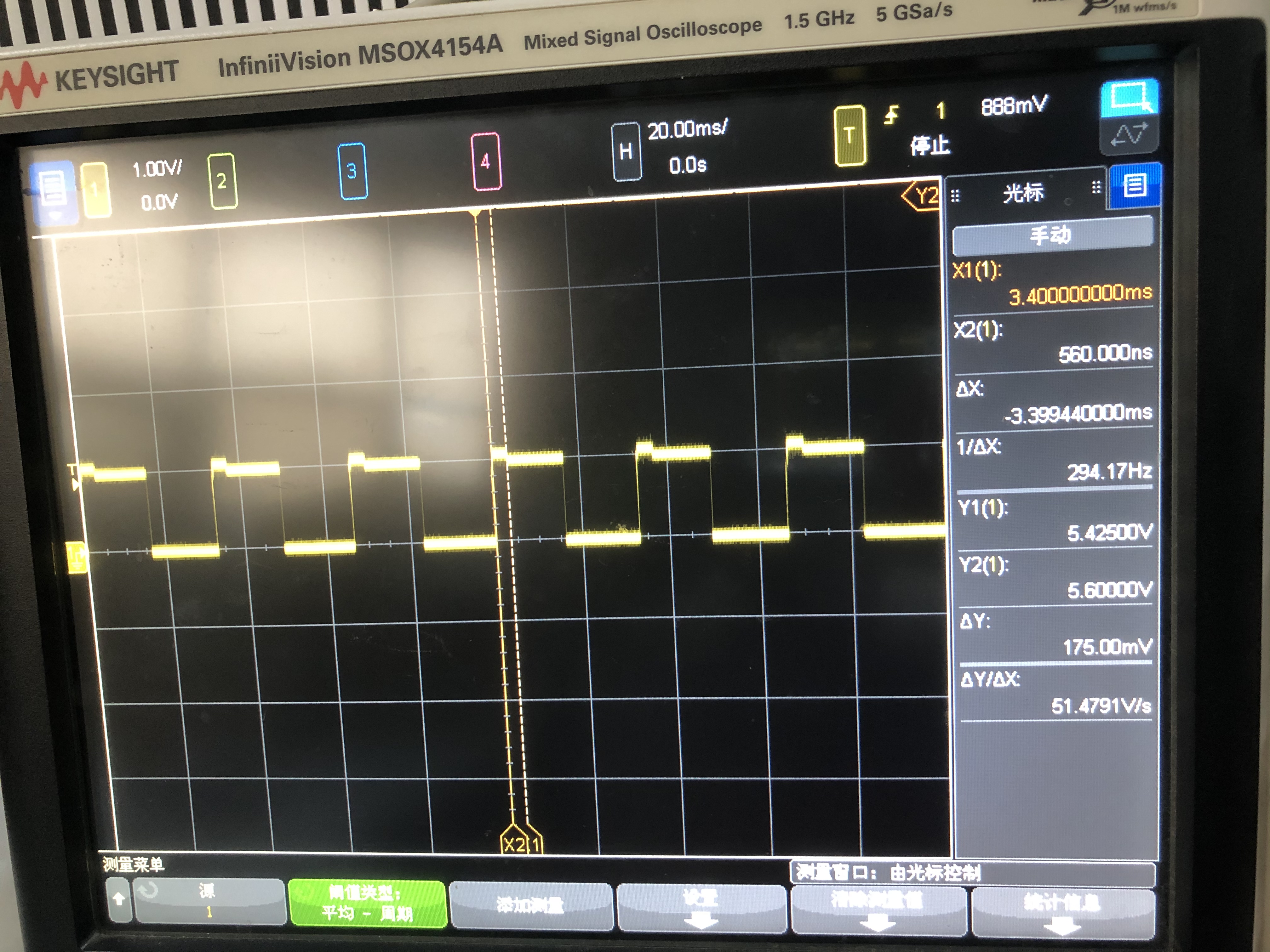
After removing C6, the IADJ and LED+ waveform becomes normal.

IADJ, but still have a discontinuity.

Thanks & Best Regards,

Sherry

  • Hello Sherry,

    If you are PWM dimming at low frequency try using the UVLO pin for PWM instead.  The LM3409 goes into low power mode when the EN pin is low, this is causing Iadj to discharge C6 and have to recharge it when EN goes high.

    Best Regards,

  • Hi Irwin,

    I have to add a diode at the UVLO pin as below, right? What is the function of the diode?

    If I use the EN pin for PWM dimming at low frequency and remove C6, is there any problem?

    Thanks & Best Regards,

    Sherry

  • Hi Irwin,

    If we use the EN pin for PWM dimming at low frequency and remove C6, is there any problem?

    Because there is some risk to achieve this function at UVLO pin. The PWM signal comes from image sensor's GPIO, and the voltage is 1.8V, and the maxim voltage of the GPIO is 3V. When doing some special test, the voltage of UVLO pin will be larger than 4V. In this way, the large voltage will comes to the sensor's GPIO pin through the diode, which may damage this GPIO pin. Therefore we can't use UVLO pin to achieve PWM dimming.

    Thanks & Best Regards,

    Sherry

  • Hello Sherry,

    You can remove C6.

    Also RUV1 limits the current that can get back to the GPIO pin, they can check how much current it can sink when high.  Another option is the drive the UVLO with a NPN or MOSFET such as the BSS123 (this will invert the PWM signal).

    The UVLO can also be clamped with a zener.

    Best Regards,

  • Hi Irwin,

    Thanks for your reply!

    The function of C6 is filtering unwanted high frequency noise at IADJ pin. If removing C6, the IADJ pin maybe easily impacted by high frequency noise, right?

    In addition, I don't understand why we still need to use IADJ pin when using PWM dimming. IADJ is used for analog dimming, why I can't leave this pin floating?

    The customer hopes to use the EN pin to achieve PWM dimming.

    Thanks & Best Regards,

    Sherry

  • Hello Sherry,

    Yes you can leave Iadj open/floating, this will set it to maximum current, 246 mV, for peak current sense.  C6 can be for filtering or other functions but it sounds like you don't need it.

    If you are going to run very low duty cycles you may run into VCC discharging and not being able to recharge using the EN pin.

    Best Regards,