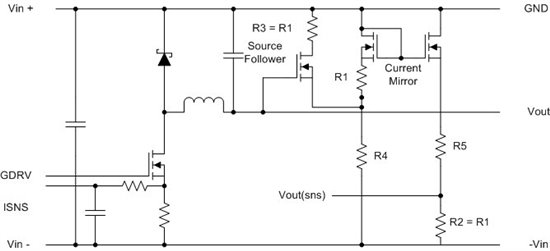
Vin = -7.7V (negative voltage)
Vout= adjustable through external controller between -5.0V and -3.0V (negative output)
Current=7.4A
Do you have a suggestion on what IC and topology I should use?
Vin = -7.7V (negative voltage)
Vout= adjustable through external controller between -5.0V and -3.0V (negative output)
Current=7.4A
Do you have a suggestion on what IC and topology I should use?