This thread has been locked.

If you have a related question, please click the "Ask a related question" button in the top right corner. The newly created question will be automatically linked to this question.

BQ2000: BQ2000SN-B5TR 3 cell Ni-mh design issue

Part Number: BQ2000

Hi there,

based off these 2 posts

https://e2e.ti.com/support/power-management/f/196/t/852555?tisearch=e2e-sitesearch&keymatch=bq2000

https://e2e.ti.com/support/power-management/f/196/t/854802?tisearch=e2e-sitesearch&keymatch=bq2000

we went ahead to make the design as follows:

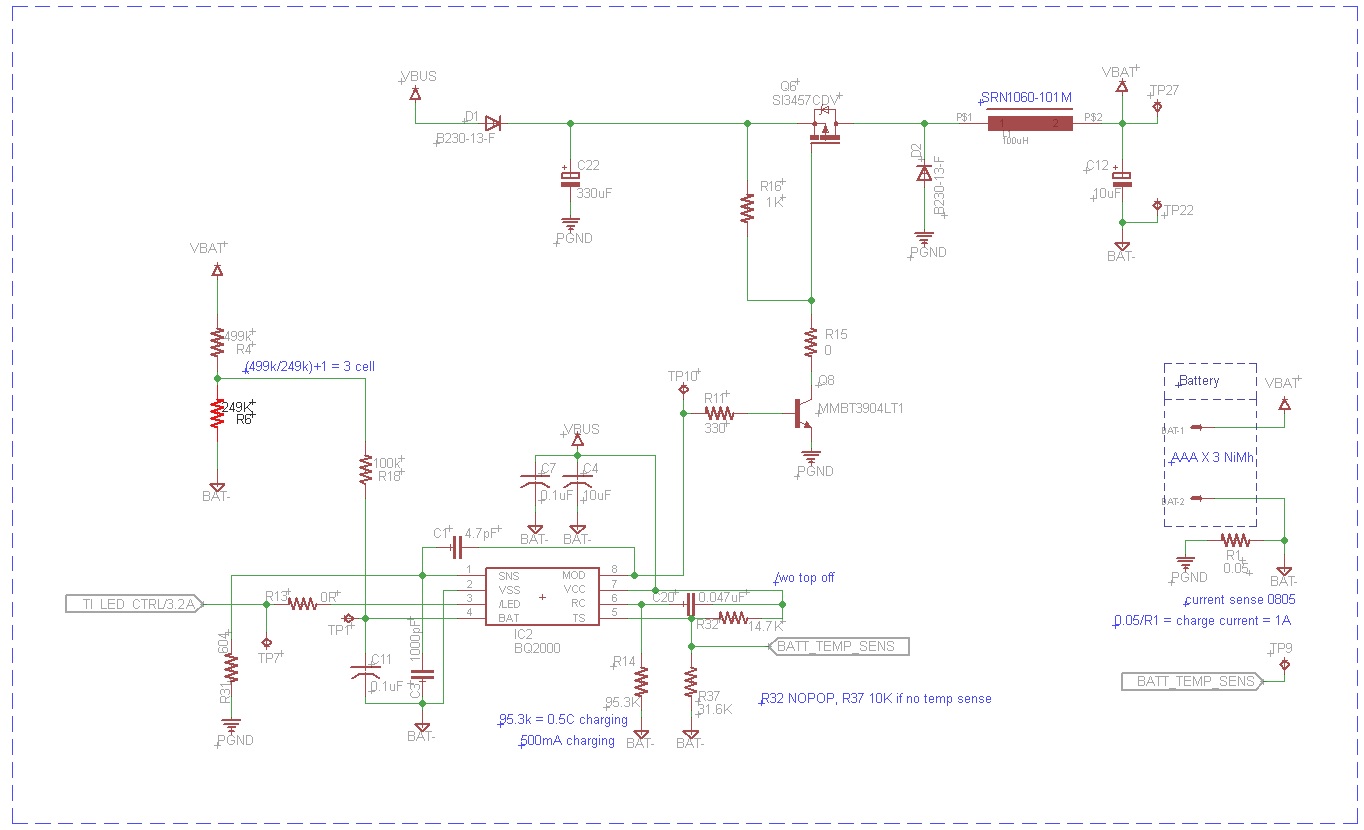
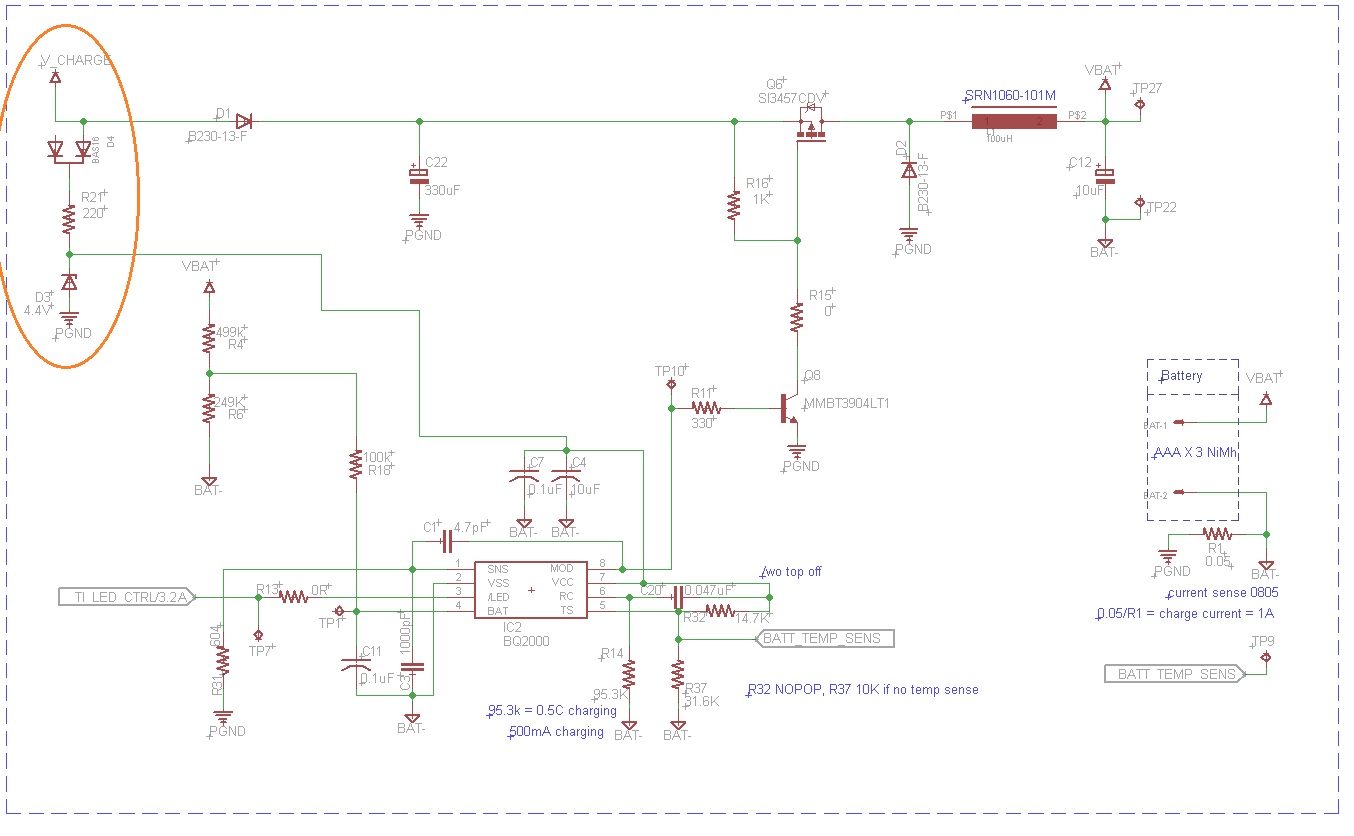
Input voltage is 5V via USB-C , charging 3 cell NiMh battery 3.6V 1100mAh , at 0.5C without topoff. The battery has no NTC hence 10k resistor pull down.

The PFET used is SI3457 as original 3455 is not available anymore, and fast switching transistors + circuitry removed.

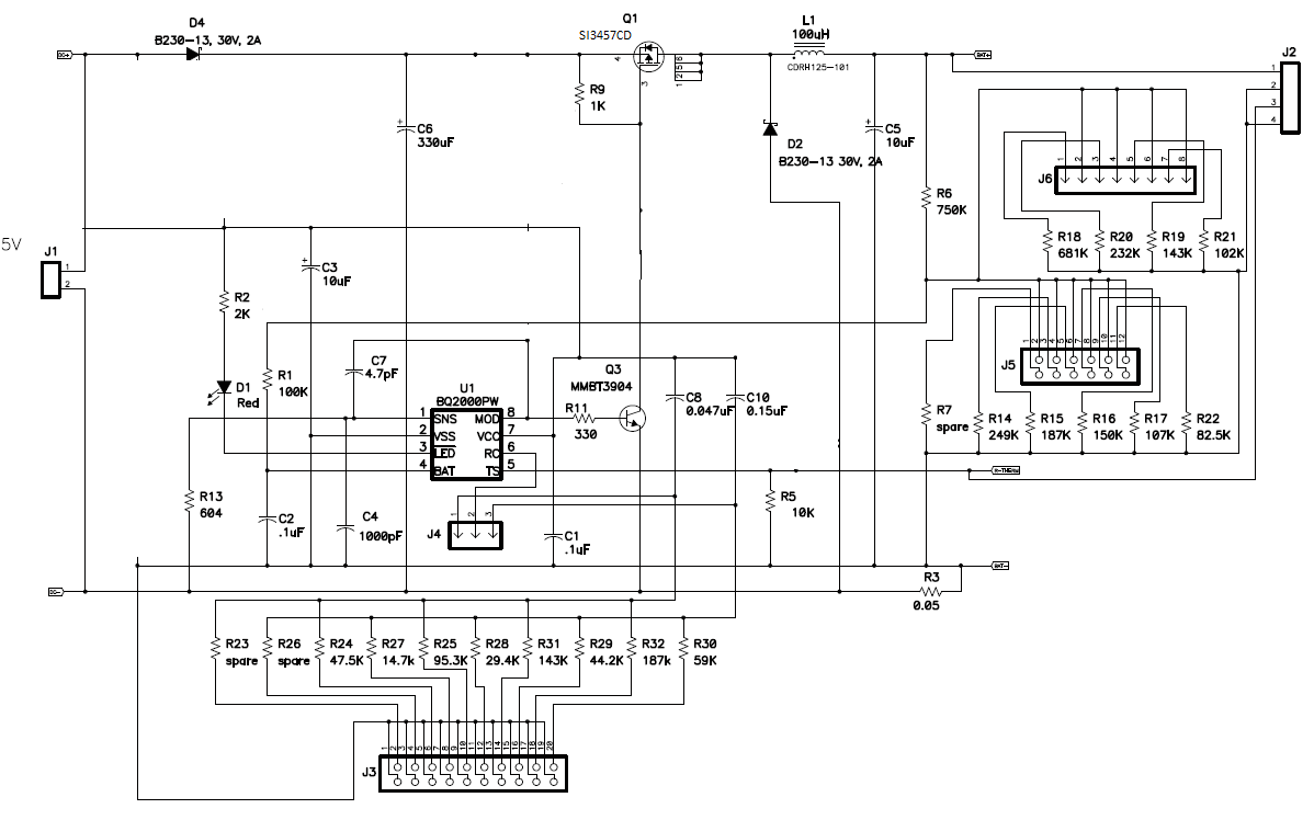
The issue we are facing now is that this circuit "seems" to be able to charge a NiMh battery , because it is able to charge a battery from 3.9V to 4.16V within 5 minutes. However using an oscilloscope to check the /LED , MOD and RC pins, I don't see the waveforms as suggested in the datasheet. 

1.) the LED doesn't change state at all despite the battery seemingly holding a higher voltage before /after / during charging.

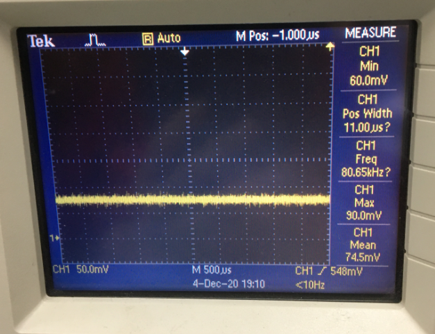
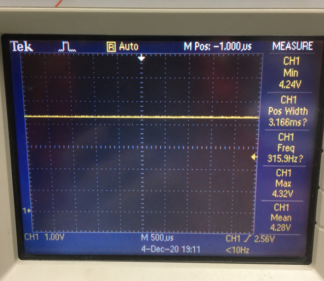
2.) the MOD pin during charging is at around 4.6V , and after cease charging goes down to 0V. However I dont see any switching as in the datasheet, just a flat 4.6V.

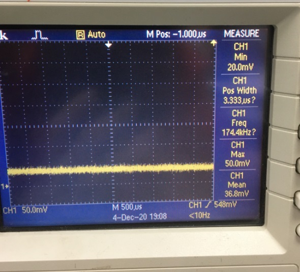
3) the RC pin also shows no state changing, the datasheet indicates that it should be switching. 0.047uF and 95.3K used for 0.5C charging and no top off config.

I hoped I have provided sufficient information for you guys to provide some insight into if the situation is normal or not , any clues would be appreciated, thx. 

  • Update: the /LED pin is not connected to any LEDs, but was left floating while probing the pin. Added back the LED +resistor, and here is the observation. 

    - If the battery is inserted, the LED doesn't light up.

    - As long as a 5V power is applied , the LED simply lights up ( no blinks) whether the battery is inserted or not. In addition we noticed that the power supply is providing ~200mA current consumption and gradually  drops off to zero while charging, meanwhile the LED simply turns on without any blinking. 

  • Hi Pete,

     I am looking into this and will get back as soon as possible. Resources are limited due to Thanksgiving week.

  • Hi Kedar, 

    thx , and happy thanksgiving.

    regards

    Pete

  • more tests were performed.

    1) we discharged the battery to 3.5V and used the BQ2000 solution to charge the battery. it charged for about 4 minutes, and then stopped charging . The battery got charged up to 3.8V . We restarted the charging , and it stopped after around 4 minutes again. battery voltage is now at 4V. The LED indicator during all this charging didnt blink or shut down.

    2.) we used a power supply for testing, providing 5V for the IC , and used a different power source for the battery charging ( tested 5v , then 6v) , nothing changed. Will test adding the quick switch transistors and see what happens.

  • Hi Pete,

      Can you show the waveform of RC, MOD, Output voltage and LED pin on scope capture as well? Please also share your schematic for me to review.

  • MOD

    RC

    LED

    VBAT

    Hi Kedar,

    attached are the requested files. On the side note, is the BQ2000 verified to work for 5V input supply ? Since this solution is a buck mode switching regulator, is it possible for nimh 3 cell to be charged using 5v ? thx

    Pete

  • Hi Kedar,

    any update ? 

    We did more tests and found something interesting.

    The power to the IC was modified as circled in orange above using a 4.4V zener ,resistor and schottky diode to do a voltage drop from the source, and we applied 6V to the circuit. When no battery was plugged, the power to the IC is 4.4V as the zener works as such. However, when the battery was plugged and then 6V power applied, the power to the IC dropped to 3.48V , but the charging seems to be working, and we could see  switching in the MOD pin around 125Hz 50% duty cycle. The charging lasted for 2 hours+ , but it did not stop charging the battery. The battery voltage reached around 4.6V and it then started to heat up, then the voltage of the battery gradually dropped to 4.45V. Can you help verify what is going on with the BQ2000, and what can be done for 5V power source to work, thx. 

  • Hi Kedar,

    any update on the situation ? We have tested quite a lot of circuits based on the datasheet and EVM,  and varied the input voltages as suggested in the datasheet, but the BQ2000 on hand does not seem to be working as specified. Any clues would be appreciated to get things on track. If you need to check the layout, please provide an email so that we can send the files in private, thx.

    Pete

  • Hi Pete,

       When battery is fully charged, the battery will heat up and this is a possible termination mechanism. The BQ2000 can work with 5V input, as long as you remove the Q4, R10, D6 circuitry which acts like a linear regulator to regulate the VCC voltage to 5V. LED should not be lit during battery absent as the pin should be high impedance.

    What is the max charge regulation voltage of your 3s NIMH? As this is a buck charger, there is a certain threshold above the battery voltage, at which input voltage is required. You have to account for voltage drop in the input path, as the voltage on VCC close to the pin of the IC is what needs to be measured.

    Have you tested your configuration on the EVM? (with disconnecting the Q4, R10, D6 circuitry)

  • Hi Kedar,

    We dont have the EVM, we have just built our own PCBA based on the reference EVM design, which is the schematic you see above provided. Since the above schematic failed to work using 5V , we have reconstructed the sample PCBAs fully restoring  the components as close as possible ( you will notice that the BAT54 is replaced by BAS16 ) as the EVM suggests to make sure things should work as the EVM indicates, and providing 10V power source for the battery charging; but things are not working properly. 

    I understand that for NiMh that it will heat up when the charge is full, and that the voltage of the battery will drop as a result of full charge and it heats up ; this seems to be a characteristic of NiMh. The max charge regulation of the 3s Nimh battery seems to be 4.6V , as that is where the voltage cease to rise and temperature builds up. 

    Some of the issues that we find weird are :

    1. When no battery is connected ,the BQ2000SN-B5TR  /BAT pin still lights up the LED. 

    2. When the battery is connected, and 10V power source applied ,BQ2000 "seems" to be at work charging ; However the VCC voltage of the BQ2000 drops to 3.48V ( is this normal ?) , the switching frequency at the MOD pin is under 1kHz ( the datasheet indicates 200khz-300khz ?) . When the battery is pulled out, the VCC restores to the zener clamp.

    3. With top off option selected, the current drawn from the power supply when the NiMh is at full charge, heating up and voltage dropping back, is still the same when it is fast charging , which indicates that the top off is not working as it should ( should it not be charging every second, not continuously and thus the current consumption should be a 1/16 of fast charge ?) . The LED pin is still a dead giveaway as it doesnt change state whatsoever. 

    We weren't expecting that many issues with a circuit that doesnt seem to be complicated; however we understand that silly mistakes could have been made that lead to unexpected issues, which is why we are suggesting a layout review should there be any mistakes that we have overseen, but maybe obvious with you guys. I assume the schematic is ok as you have not suggested any issues with it otherwise. Any help would be appreciated, thx.

    Pete

  • Maybe if issue 1 is resolved, the other issues will get fixed.

    Why is the LED pin lighting up when no battery is connected ? what are the mechanisms for the IC to detect that a battery is present ?

    I have probed the MOD pin meanwhile, and unsurprisingly, the MOD pin is high providing 4.7V ( VCC 5V) which makes no sense. Have you or anyone at TI seen such issue or similar events previously ? Any clues are appreciated , thx.

  • Hi Pete,

      Unfortunately I have not seen this issue before. The VCC dropping to 3.8V when battery is present leads me to think that there might be a current clamp on your input source itself, which is causing the VCC to droop to below the valid VCC. As this is an older part, we have limited resources available so I would recommend procuring an EVM to be able to test and observe your system conditions on the VEM