This thread has been locked.

If you have a related question, please click the "Ask a related question" button in the top right corner. The newly created question will be automatically linked to this question.

TPS65217: sometimes not starting at power up

Part Number: TPS65217
Other Parts Discussed in Thread: AM3354

Hi,

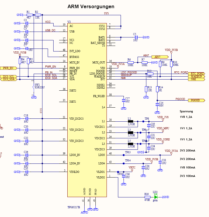
we have TPS65217B and AM3354.

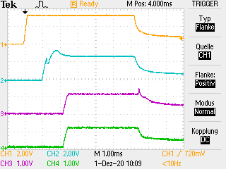
Sometimes it happens that the system is not booting, i don't know why. When this happens LD2 is on for a very short time and then goes off.

Any ideas what i can do ?

Where and what should i measure ?

  • Peter,

    Do you have an oscilloscope capture showing the issue occurring?

    Can you measure AC (VCC), BAT, LDO1, and LDO2?

    Is anything connected to USB_DC?

    When the issue occurs, is AC removed and then re-applied? In other words, is there a brown-out condition on the main supply (+24V)? 

  • Hi Brian,

    nothing is connected to USB_DC, i removed C3 and tied it to ground.

    I also removed C5 and tied BAT_SENSE to BAT1 and BAT2

    I'm using a standard power supply for development 0...32V 0...3A.

    I have a condensator block and put it between the powersupply and the board,

    but it happens also, so there should be no brown-out condition.

    After re-appliying the main power when the issue occurs, it's working in most cases....but customer

    has said to me "he needs sometimes 10 tries."

    When this issue happens and i press SW1 all is good.

    I also think that this issues happens, when the board was long time without power.

    I try to measure the signals, just have to wait for an oscilloscope from a colleague,

    What do you mean with BAT ( pin 4,5 and 6) ?)

  • Hi Brian,

    here the oscillocope screenshots

    Ch1: 24V main Power Supply

    Ch2: 5V VCC

    Ch3: VLDO1

    Ch4_ VLDO2

    #1 the good state

    #2 the fault state

  • Hi Brian,

    some more Infos

    I reemoved R9 (Wakeup to VDD3V3b) don't know why this was made.

    And here the EXT_WAKEUP at Processor

    stille the same issue ;-(

    here is the processor PGOOD, SYS_NRST and RTC_PORZ

  • R12 0 Ohm

    R13 not populated

    C14 not populated

    Some new Measurments

    Ch1: VCC = AC

    Ch2: SYS

    Ch3: VLDO1 = VRTC

    Ch4: VLDO2

    #1 good state

    #2 fault state

  • Hi Brian,

    could it be possible that our connection VIO --> LDO3 is the main cause of this behaviour ?

    this should be connected to VLDO1 or ?

  • Hi Brian,

    again 2 measurements

    Ch1: VLDO1 = VRTC

    Ch2: VLDO2 = Power for LD2

    Ch3: VLDO3 = VDD_3V3A

    Ch4: PGOOD

    #1 good state

    #2 fault state

    as you can see in the fault state PGOOD is not reaching high level.

    Brian what do you think ?

  • Peter,

    This is good information. I think there is enough for me to review and provide recommendation, but it will take some time to review.

    Tomorrow is national holiday in U.S. and I will be back in the office on Monday, November 30th to continue debug effort.

  • Hi Brian,

    thanks for the info.

    I just want to inform you that i tied VIO Pin 18 to VLDO1 and made some measurements

    -> still the same issue

    Ch1: VLDO1

    Ch2: VLDO2

    Ch3: VLDO3

    Ch4: PGOOD

    #1 good state

    #2 fault state

    Happy weekend and i'm awaiting your response next week.

  • Hi Peter,

    As Brian mentioned, he is out of office due to public holidays and he will provide you the feedback after he comes back on Monday.

    Regards,

    Murthy

  • Peter,

    Referring to the power-up sequence for TPS65217B, shown in Powering the AM335x with the TPS65217x, you are looking for which rail fails to turn on and reach the desired voltage. 

    We know LDO2 = 3.3V is good, so we look at rails after this:

    • LDO3 = 3.3V, and in the scope shots you provided it looks like LDO3 is reaching 3.3V correctly
    • LDO4 = 3.3V --> does this regulator reach 3.3V as expected?
    • DCDC2 = 1.1V --> does this regulator reach 1.1V as expected?
    • DCDC3 = 1.1V --> does this regulator reach 1.1V as expected?

    My expectation would be that one of these rails: LDO4, DCDC2, or DCDC3 do not turn on correctly.

    Note that the inductance and output capacitance used in your design, L3/L5 = 2.5uH and C21/C24 = 22uF but the recommendation is Lx=2.2uH and Cout=10uF. If either DCDC2/3 fail to turn on, this mismatch could be one explanation for why there is an issue. 

  • Hi Brian,

    that's interesting thus i am a software developer i ask my collegues why there are different values populated.

    Here the next measurement , does this proof your expectation ?

    Ch1: LDO3

    Ch2: LDO4

    Ch3: DCDC2

    Ch4: DCDC3

    #1 good statre

    #2 fault state

  • Yes, it shows that LDO4 never reaches 3.3V and stays there in the fault case. Because LDO4 != 3.3V after 5ms, all rails are disabled.

    Also, it shows in both cases that LDO4 has a strange glitch during ramp up in both the good case and the fault case, and this is unusual for an LDO.

    Can you disconnect LDO4 from all loads and try the tests again? The output capacitor for LDO4 still needs to be present, but nothing else downstream. Then you can analyze the loads on LDO4 one-by-one to determine which one might be causing the issue and why it happens sporadically.