When the bq34z100-g1 gas gauge (GG for short) is configured for four-led mode, HDQ is required as the main communication protocol between it and the host mcu.
What is required to program the GG during manufacture while it is configured as described above?
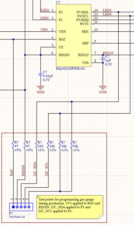
From the data sheet, it seems like BAT, REGIN both need 3.3V (technically 2.7 - 4.5v) applied to them and I2C_SDA on P3 and I2C_SCL on P4.
Do P3 and P4 need 10K pullup to 3v3 resistors?
My thought was to have a 5 pin pogo connection on the board and before the board has been energized connect 3v3 to BAT, REGIN and the 2 I2C 10K pullups and then flash the configured FW onto the GG over the I2C bus. Is that possible? See design below for rough sketch reference.