This thread has been locked.

If you have a related question, please click the "Ask a related question" button in the top right corner. The newly created question will be automatically linked to this question.

BQ76930: Short Circuit Protection

Part Number: BQ76930
Other Parts Discussed in Thread: BQ78350-R1, , TIDA-00449

Hello.


We are trying to build a BMS using the BQ76930 AFE and the BQ78350-R1 Fuel Gauge. Design based on EVM. Generally, it works fine, but we not sure if short circuit protection works properly. We are using 10S4P battery configuration. We tested with 5 and 10 mOhm shunt resistors, also we tested with different SCD delay 70-100uS, as a result, all times CHG and DSG FETs and shunt resistor were damaged. After we busted few FETs, we had added bulb as load and continue testing. A bulb has huge power consumption at the start, more than 50 Amps it helps emulate SC in "safe " mode, we recognised that SCD delay had been working not properly.

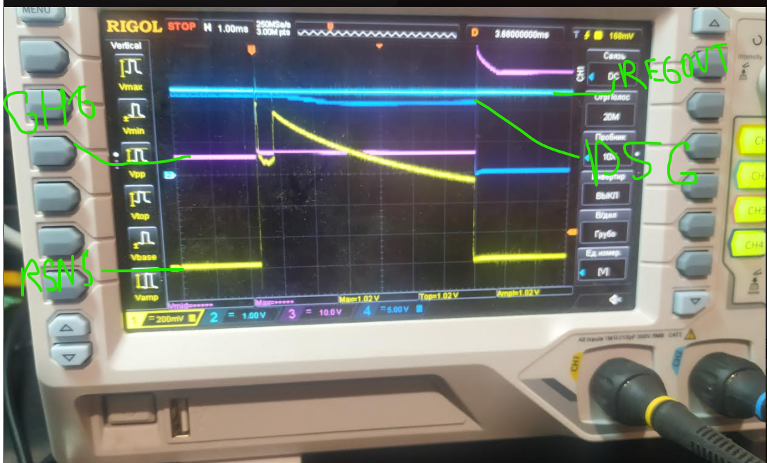
Figure 2.Test with bulb. (Yellow is the voltage across the sense resistors, Rsens -10mOhm)

As you see it's wasted around 6+mS for disable FETs.

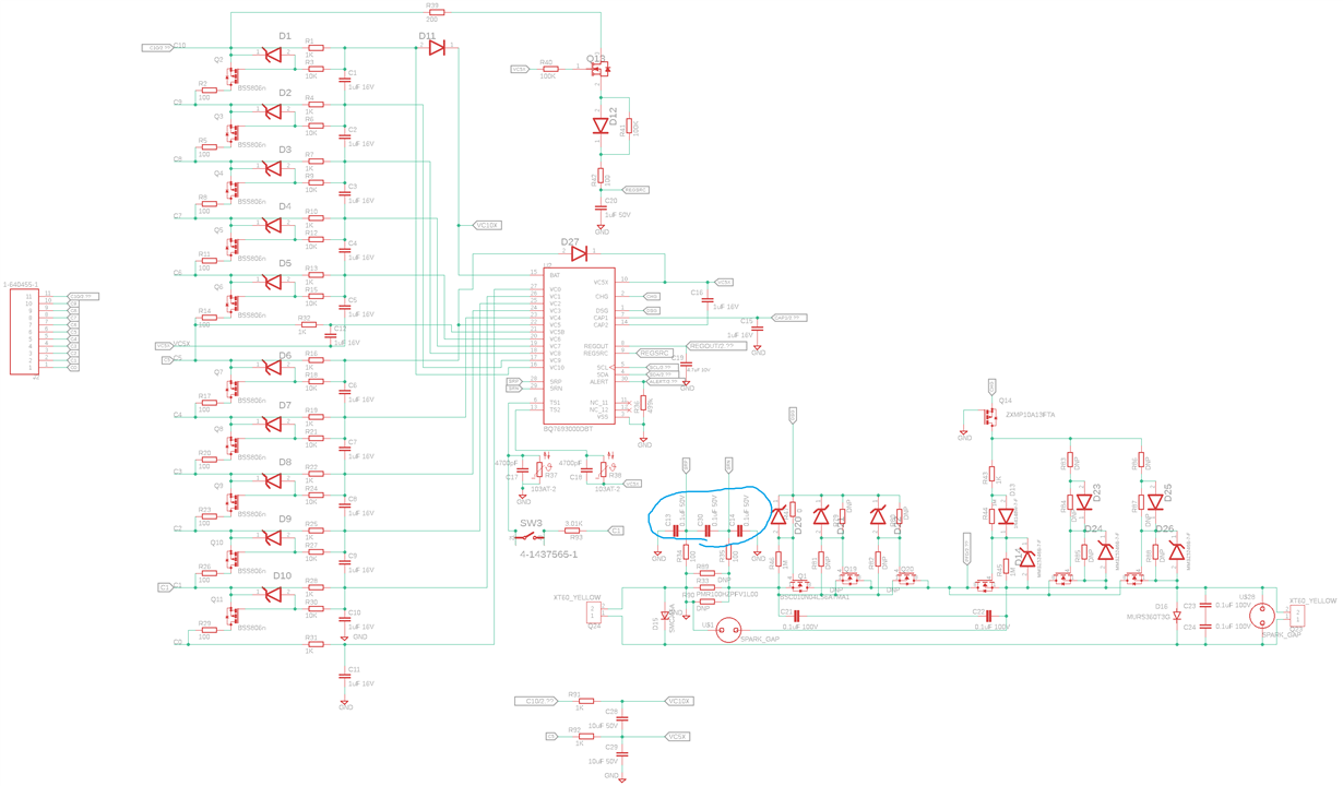
Figure 2.BQ76930 schematic (Was used 1 CHG FET and 1 DSG FET and 1 shunt )

After a few experiments, we have changed C13, C14 and C30 capacitors to 1nF and got not bad result like 150uS when short circuit discharge delay is 100us. But when we had removed the bulb and had made SC test CHG and DSG FETs and shunt resistor were damaged.

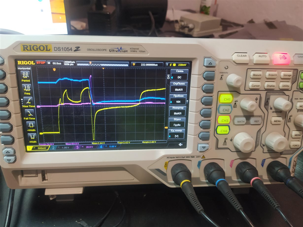
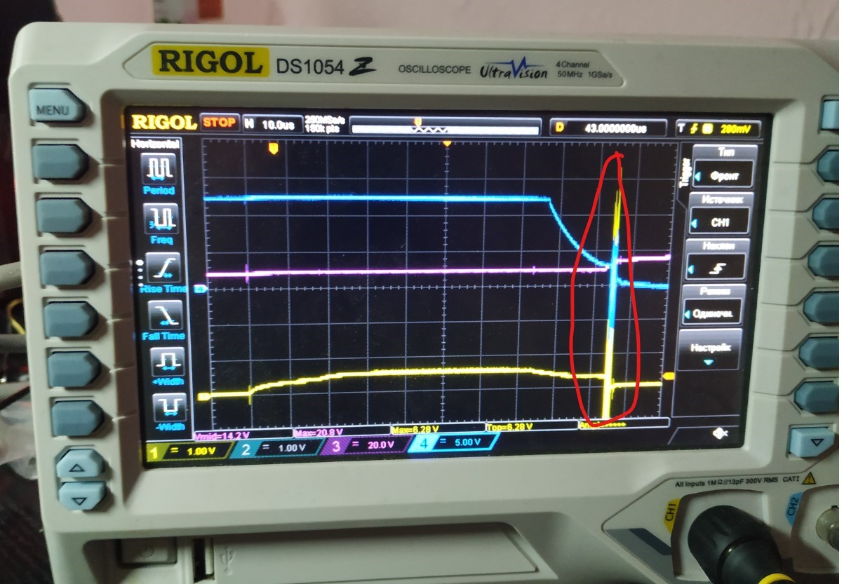
Figure 3.Short-Circuit Test(Chanel1 is the voltage across the sense resistors, Chanel 3 is the CHG FET gate voltage, Chanel4 is the DSG FET gate voltage, Rsens -10mOhm. Components were damaged). 

What minimal SC delay? 70uS?

Strange situation with CHG FET gate, could you confirm is it ok?

Do you have some recommendation to solve it an issue?

  • Hi Aleksandr,

    The description of the DSG not turning off until about 6 ms after the short is typical of the part losing the VC5X voltage during the short circuit. If the VC5X voltage pulls into VSHUT range quickly the part does not turnoff but the timing logic has lost its power supply, the FETs remain on until they turn off later when the FETs have heated significantly or already failed.  Your schematic shows the typical Rf and Cf values of 1k and 10 uF, this issue is more expected when small value components have been used for Rf, Cf, or Rc which causes VC5X to pull down too quickly.  Check for substitute/wrong value parts at R91, R92, C28, C29 or the input filter resistors R1, R4, etc.

    The shorter SCD delay time gives more time margin as the power supply filter capacitors discharge during the SCD event.  The minimum setting is 70 us nominal.

    The filter on the SRP, SRN will have an impact on the SCD response time, normally with the common values it is not significant.  It seems you observed a significant change.  It is a multiple input filter, but if you approximate the load on SRN as 0.2 uF and 100 ohm input, the time constant is 20 us.  You are driving far past the threshold so the contribution should not be too large.  The 1 nF caps would certainly be faster.  You might check that the correct value was initially used and that the resistors are the intended 100 ohm. 

    When DSG turns off the cells will normally have an inductive response raising their voltage so that of PACK+.  When connected through the short circuit to PACK- PACK- also pulls up and takes the charge FET gate up through the forward biased zener diode. This will normally drop off quickly, but it depends on how long the short is attached.  If the short remains the gate will be held near the PACK+ voltage.  So it is common to see the CHG gate voltage go from about 12V when on and during the SCD timing to a peak of 50-80V perhaps at turn off and settle to about 40V until the short is removed from PACK-.

    Pins 11 and 12 should connect to CAP2 (pin 14) but that should not affect SCD behavior.

    Hope this helps you track down the issue.

  • Hello. Thank you for your answer. We did some changes according to your advice from the previous message related to VC5X(it looks like works faster and better), also we have changed and added few transistors (now we uses 2 BSC096N10LS5 CHG and 2 BSC096N10LS5 DSG ) also was changed R47 resistor to 100 Ohm.
    After a few tests, almost nothing was changed(burned transistors, shunt and IC). According to oscillogram it worked not bad and tried to disable transistors in a short time but something goes wrong.

    Figure 4.Test with bulbs. (Chanel1 (Yellow )is the voltage across the sense resistors, Chanel4 is the DSG FET gate voltage Rsens -10mOhm)

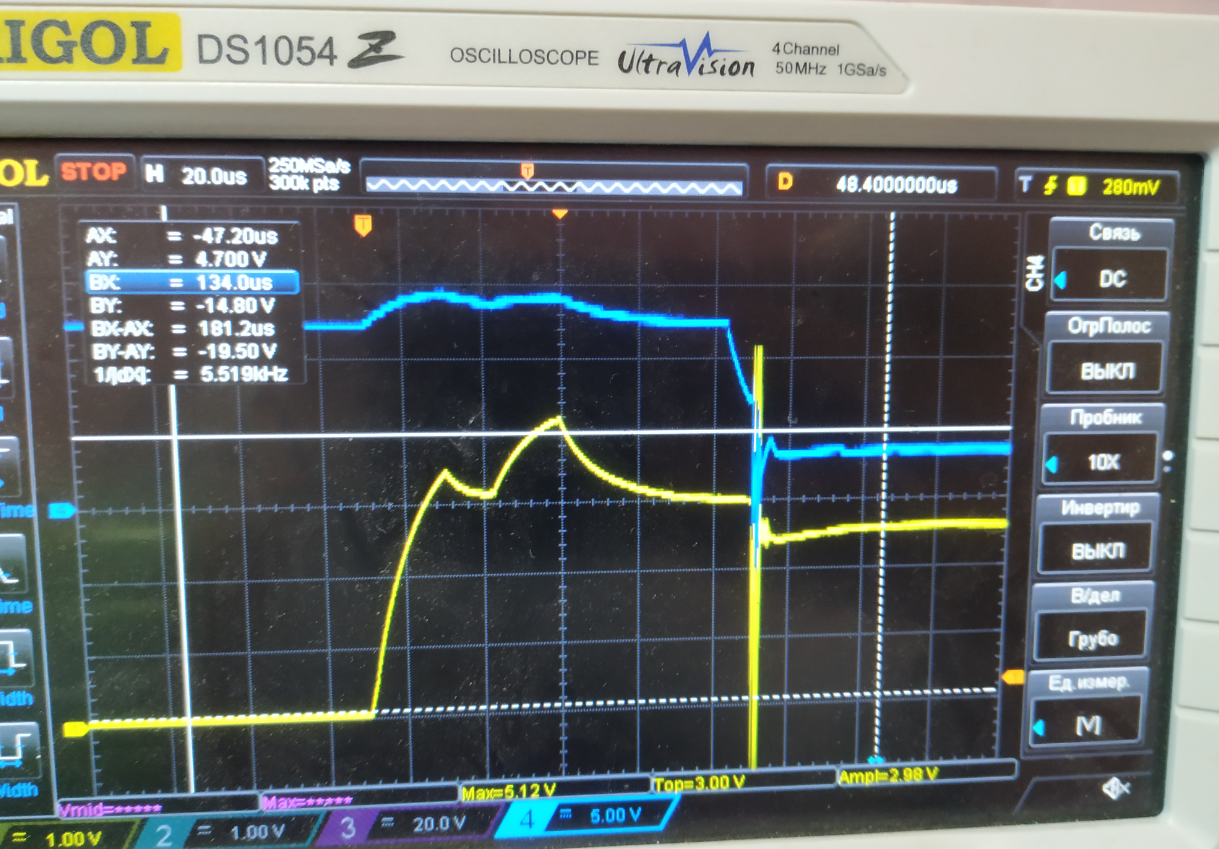
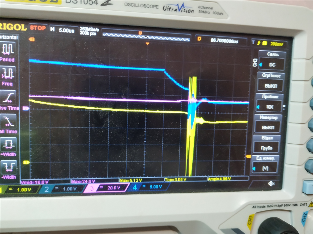
    Also, we noted that something strange happened during falling edge.

    Figure 5. SC test. (Chanel1 is the voltage across the sense resistors, Chanel 3 is the CHG FET gate voltage, Chanel4 is the DSG FET gate voltage Rsens -5mOhm)

    Figure 6. SC test. (Chanel1 is the voltage across the sense resistors, Chanel 3 is the CHG FET gate voltage, Chanel4 is the DSG FET gate voltage Rsens -5mOhm)

    What do you think about it?

    Do you have any ideas?

    Thank you.

  • Hi Aleksandr,

    It looks like your parallel FETs are oscillating at the point of turn off, and this can cause FET failure. Common solutions in the circuit are to use small resistors or beads from the common drive resistor to the individual gates.   Look for recommendations from industry or educational sources. You might look at an application note from your FET supplier "Paralleling Of Power MOSFETs For Higher Power Output" which has a detailed discussion of the phenomena and where they indicate "Partial gate decoupling (approximately 10%) may be required for parasitic oscillation control".  The ferrite bead decoupling was used on TIDA-00449 and some other TI designs, others have used resistors.  Some FETs don't seem to oscillate in parallel, testing on the BQ76930EVM with 2 FETs in parallel did not manifest the oscillation while the TIDA-00449 required the beads.