This thread has been locked.

If you have a related question, please click the "Ask a related question" button in the top right corner. The newly created question will be automatically linked to this question.

WEBENCH® Tools/LM63625-Q1: TI WEB bench based design didn't work

Part Number: LM63625-Q1
Other Parts Discussed in Thread: LM2596

Tool/software: WEBENCH® Design Tools

I am using LM63625DQDRRRQ1 as a DC-DC step down converter for my custom PCB design for automobile light control application. I used TI’s WEBBENCH power design and used all the components as per recommended design offered by TI in datasheet for LM63625 series except that I have RT connected to GND and RESET_IN is floating.
My requirement is 3.3V@2-2.5A , with input voltage of 9-36V
The output was quite stable with 3.310V output when Input voltage was 12V. But the IC got fried with a sparky blow with 24V input supply.
Although the IC is rated for input voltage range of 3.5V -36V. I can’t figure out, what is wrong with it.
Is there anything that I am interpreting wrong in datasheet or the used IC which is supplied to me in VQFN package is wrong?


Regards,

Balbir

  • Hello Balbir,

    Can you please send over your schematic and layout for review?

    Could you also send over some screen shots of the input voltage, output voltage, and SW node voltage (on the same screen if possible) for the case when Vin=12V as well as for the case when Vin=24V and you see the damage?

    Thanks,

    Harrison Overturf

  • Hi Harrison,

    Please find the attached schematic and the TI WEBENCH  design.

    A bit more info as below.

    I have this switching regulator on my custom designed PCB with AVR microcontroller. I am using the switching regulator to power up microcontroller and other peripheral & my input would be coming from the vehicle battery.  

    I had a  combination of linear regulator and LDO before and it was working okay except the amount of heat produced by linear regulator didn't seem ok with my application. 

    I tried three different regulator IC's and each one gave me same results. Unfortunately I didn't get a chance to capture the  input/output. I only measured my output with multimeter & it was perfect 3.3V at 12V input. just to mention I am supplying the input from the  SMPS. 

  • Hi Balbir,

    What is the purpose of Q1 and R1 and R2?

    From what you describe, it sounds like the voltage present at the VIN pin may be exceeding the absolute maximum of the device and causing the sparky blow to occur. If you have long lines connecting your battery to the LM63625-Q1 device then the parasitic inductance of these lines form a resonant LC circuit with the input capacitors which can form large transient voltage spikes when the device is turned on.

    One way to dampen these transients would be to include a large electrolytic input capacitor with a moderate ESR at the input. A voltage rating of 50V would ensure the capacitor is able to handle any transients that would be present on the input line.

    If you have an oscilloscope handy, you can check for the presence of these transients at turn ON for the 12V input case. Measure the peak spike voltage present, then run the test again with an electrolytic capacitor added to the input and compare the peak voltage present at the VIN pin.

    Let me know the results of these tests and if the IC is still fried when 24V input is present. Please note that my responses may be delayed due to the Thanksgiving holiday, but I will respond by the end of day 11/30.

    Thanks,

    Harrison Overturf

  • Dear Harrison,

    Thanks for the prompt reply.

    Q1 in the design is for reverse battery protection and R1 & R2 forms the voltage divider network use to take portion of the battery voltage so that we can measure the level of battery voltage as well.

    The voltage across R1 will be connected to the microcontroller input hence measured there.   

    Your solution make perfect sense in theory and I will definitely test this and update you on this soon.

    Thanks for your help & Happy Thanksgiving.

    Regards,

    Balbir

  • Hi Balbir,

    Thank you, I look forward to your reply.

    Regards,

    Harrison Overturf

  • Dear Harrison,

    I hope you had a wonderful Thanksgiving.

    Sorry for a very late reply. I didn't receive my components in time so couldn't create a working circuit to take the measurements.

    Finally, I received the parts today and was able run a test.

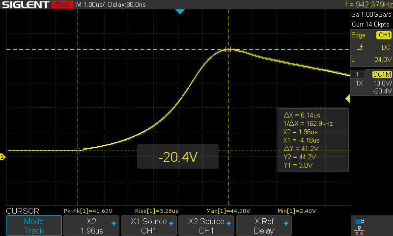
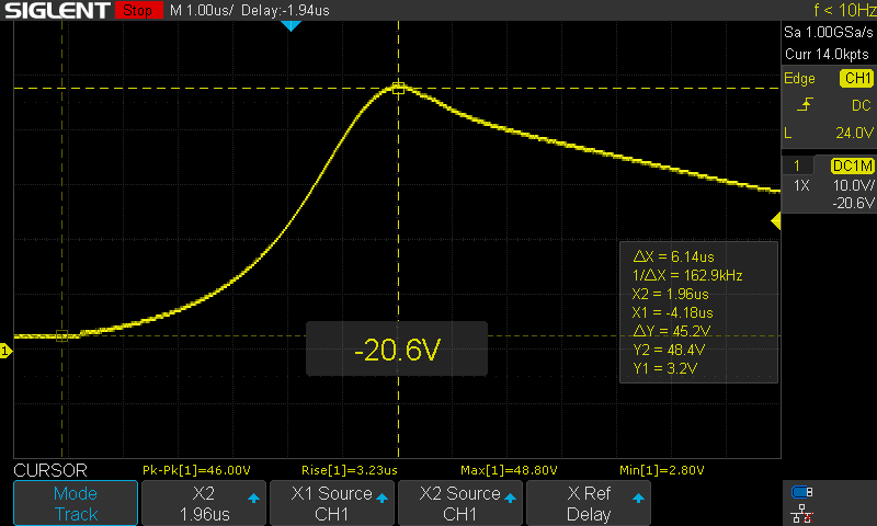
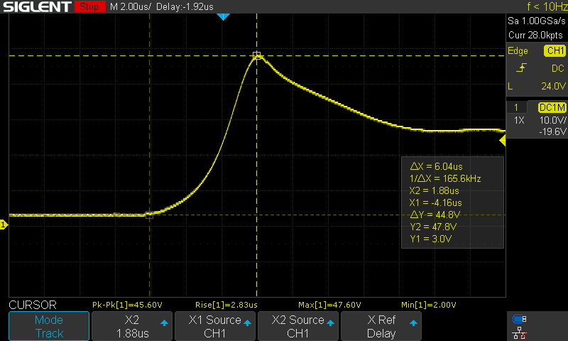
    I started with 12V as input and raised the voltage until 24V. Circuit was working fine until I toggled the manual throw switch which I have connected in between  the SMPS and regulator circuit. The moment I toggled the switch the IC was dead. then I captured the Vin transients by toggling the switch.

    Please find the attached pictures.


    By looking at the above pictures it became clear that switch transients are the main issue here.

    Just for the information I didn't use the R1 & R2 Resistors and following picture show the test point location.

    I think I should discard this whole circuit and probably design something more reliable and robust. I have seen ST microelectronics has a diverse range of switching regulators. Can you please share your valuable opinion.

    Regards,

    Balbir

  • Hi Balbir,

    The LM63625 is only a 36V rated device. TI has many robust converters that can handle your input transient.

    You can enter your conditions in the tool and find a higher voltage rated device:

    https://webench.ti.com/power-designer/switching-regulator?update=1&powerSupply=0

    Regards, Jason

  • Dear Jason,

    Switching to something with higher input voltage rating is definitely what I am going to do.

    From a designer point of view I was making effort to find a way to suppress this transient.

    Do you think using a bigger electrolytic capacitor will resolve the issue. Just for an example I purchased a DC-DC convertor module based on LM2596 which is rated at 5-30v, but still works fine with the same circuit.

    It has  100uF electrolytic capacitor at the input along with a smaller MLLC.

    It wasn't heating at all, but since I had no current draw until now so could be because of that.

    Regards,

    Balbir

  • Hi Balbir,

    Adding a bulk capacitor can can be helpful. Try adding one after the switch and see if it reduces the overshoot.

    Also, there are voltage suppression components like zener diodes and transorbs that can help suppress the voltage.

    Regards, Jason

  • Hi Jason,

    Thanks for quick reply & sending the valuable suggestion to use the Zener diode or a transorb.

    I m sure this will resolve my problem.

    Kind regards,

    Balbir