Other Parts Discussed in Thread: LM74610-Q1, TPS2121
Hi,
I have tow identical power supplies sharing the same load and are supposed to work at the same time. Each one is done by 3 AA 1.5 batteries in series (3.6V to 5.4V operating range).
So, I am locking for a solution that can protect the board and the batteries in the following cases :
- When both supplies are wrongly inserted
- When only one supply is wrongly inserted and the other is not
I found the LM74610 and LM66100 which I can use for my purpose. I think LM66100 is suitable for my application for its cost efficiency, minimal design and power consumption (quiescent current is less than 1µA in normal conditions).
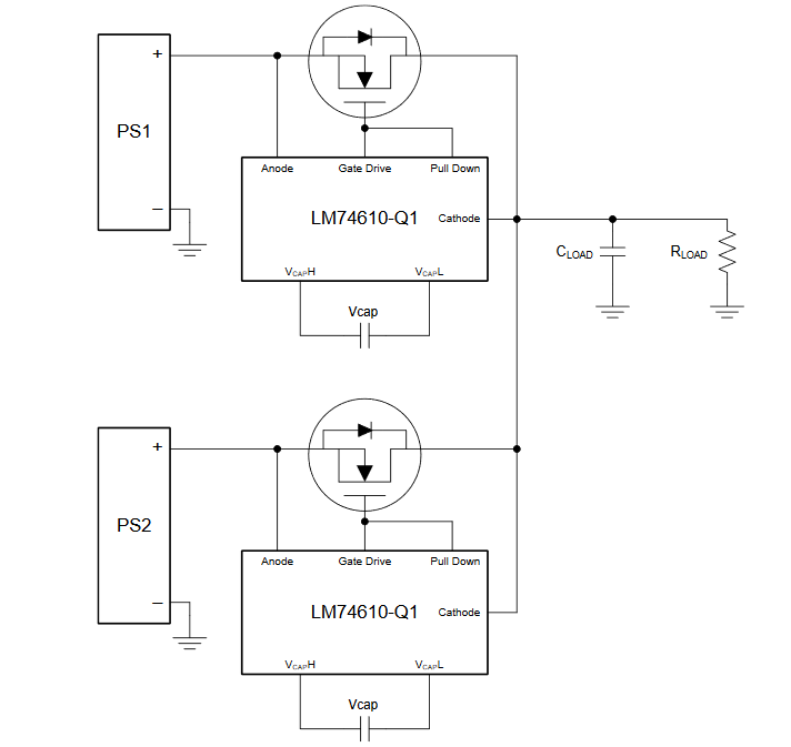
I can use it this way :
But I'm not sure about two things
One is the pulse/peak current that this switch can provide :
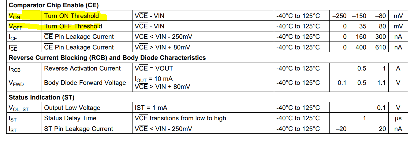
I see in the datasheet page 4 in 6.1 section : Maximum Pulsed Switch Current (≤120 ms, 2% Duty Cycle) : 2.5A
While, my board can have current bursts of 2A due to a cellular module in GPRS mode. The pulse width is 611µs every 4.6ms
I don't know if this is critical for my application's current specs.
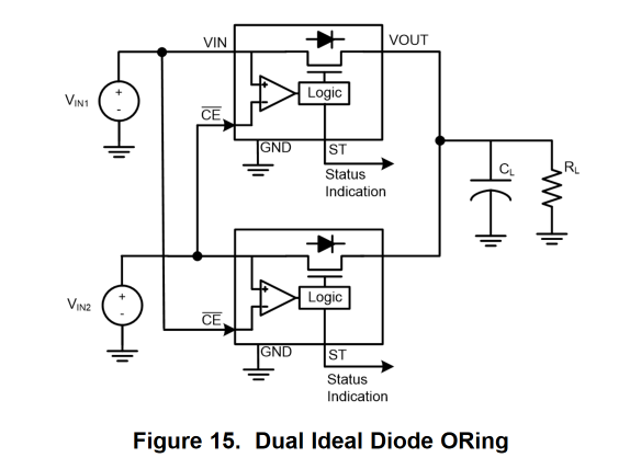
The other is that Vin1 and Vin2 are the same :
In normal operation, will both LM66100 be ON or just one ? How the setup above can deal with two identical power levels ?
Is there any other things I should take into consideration ?
Would this solution work ?
Thanks,