This thread has been locked.
If you have a related question, please click the "Ask a related question" button in the top right corner. The newly created question will be automatically linked to this question.
Our customers are considering placing Zener diodes and resistors for the purpose of ESD protection for TPS621361. I would like you to answer the following questions.
1. Is there any operational problem with placing a Zener diode or TVS diode in the immediate vicinity of each pin, such as the VOS pin?
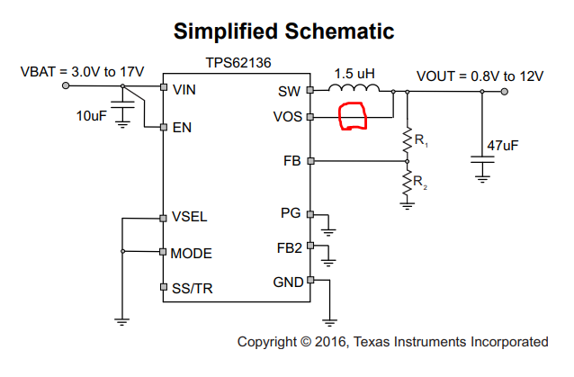
2. We are also considering inserting a resistor in the red circle in the circuit diagram below to protect the ESD of the VOS pin. Is there any operational problem if this method is used?
Best Regards,
Y.Ottey
Hi Y.Ottey,
The circuit diagram is failed to upload. Please re-upload.
Amod will response to you soon.
Thanks,
Lishuang
Hi Lishuang
Thank you for your reply.
I re-uploaded the schematic.
Regards,
Y.Ottey
Y.Ottey,
A resistor between VOS and Vout is not recommended as it can interfere with the internal control loop and also may cause regulation issues. For detailed help on ESD protection, I am forwarding these questions to the right team.
Thanks,
Amod
Hi Amod,
Thank you for your reply.
The number one question I sent in my first post was answered as follows:
”For detailed help on ESD protection, I am forwarding these questions to the right team."
As mentioned above, is it okay to recognize that the ESD protection IC team has confirmed this?
I have received a request from our customers for an early response.
Therefore, I would be grateful if you could get a reply as soon as possible.
Regards,
Y.Ottey
Y.Ottey,
Yes this post has been redirected to the right team and will respond to it.
Thanks,
Amod
Hello Y.Ottey,
I'm happy the help answer your questions.
For the output pins, I would consider using the TVS1400 or TPD2E007 since the output voltage max is 12 V.
Please let me know if you need any clarification on this or have any more questions.
Regards,
Matt Smith