This thread has been locked.

If you have a related question, please click the "Ask a related question" button in the top right corner. The newly created question will be automatically linked to this question.

BQ51050B: Intermittent charging

Part Number: BQ51050B
Other Parts Discussed in Thread: BQ51013B

I'm bringing up a board with the bq51050B and I'm running into problems — I would appreciate any advice.

The design is almost exactly the reference design from the datasheet. I even kept the starting values of passives the same, as my coil is the Wuerth Elektronik 760308103205, an 11µH coil. I'm charging a 900mAh battery.

The circuit does start up, but usually (though not always) quickly degrades into on-off cycles, turning on roughly twice per second. I do not know why, but I've also seen the device sometimes indicate continuous charging (CHG low) in a stable way. I haven't figured out what could influence this.

I thought it could be noise on the thermistor connections, so I tried placing a 100nF cap across the thermistor. That did reduce the noise, but didn't affect the symptoms.

I also tried the slightly larger 760308103204 coil (16.7µH), same results.

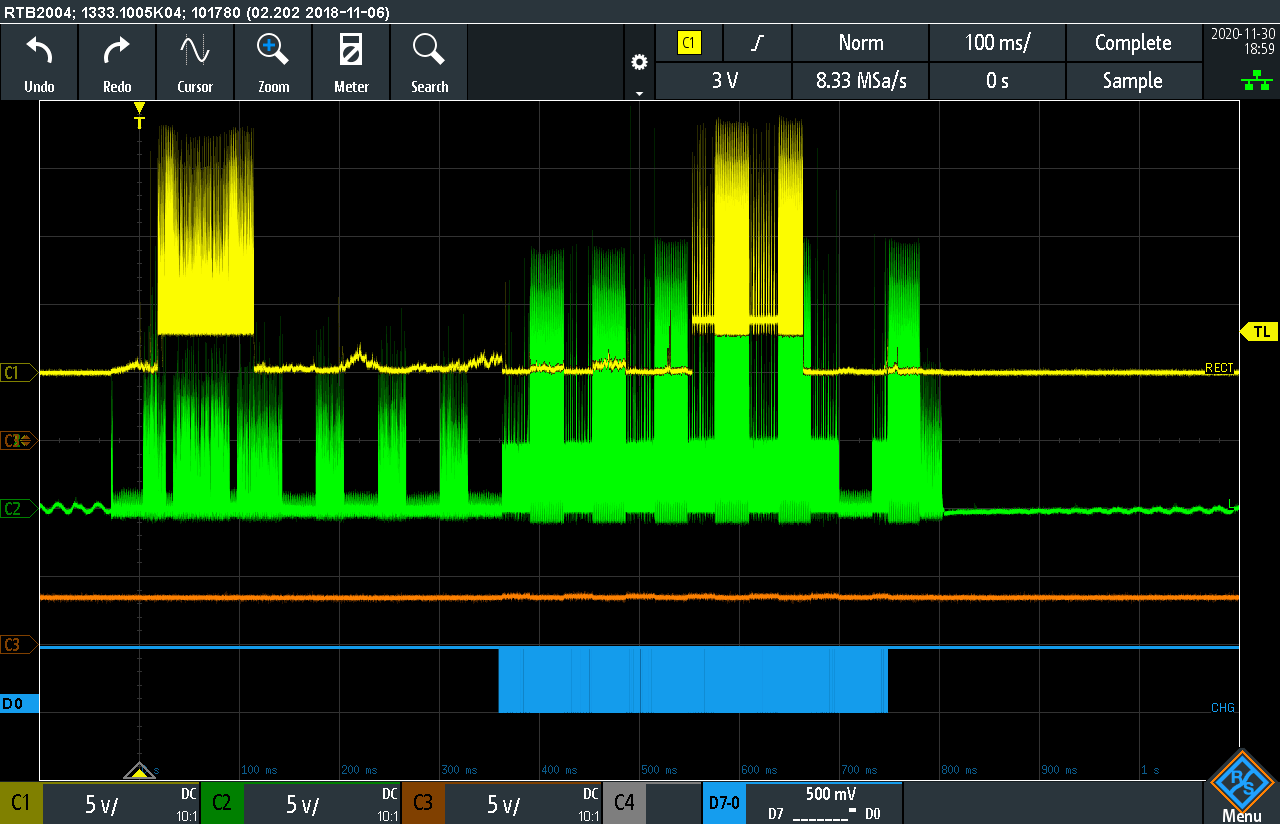
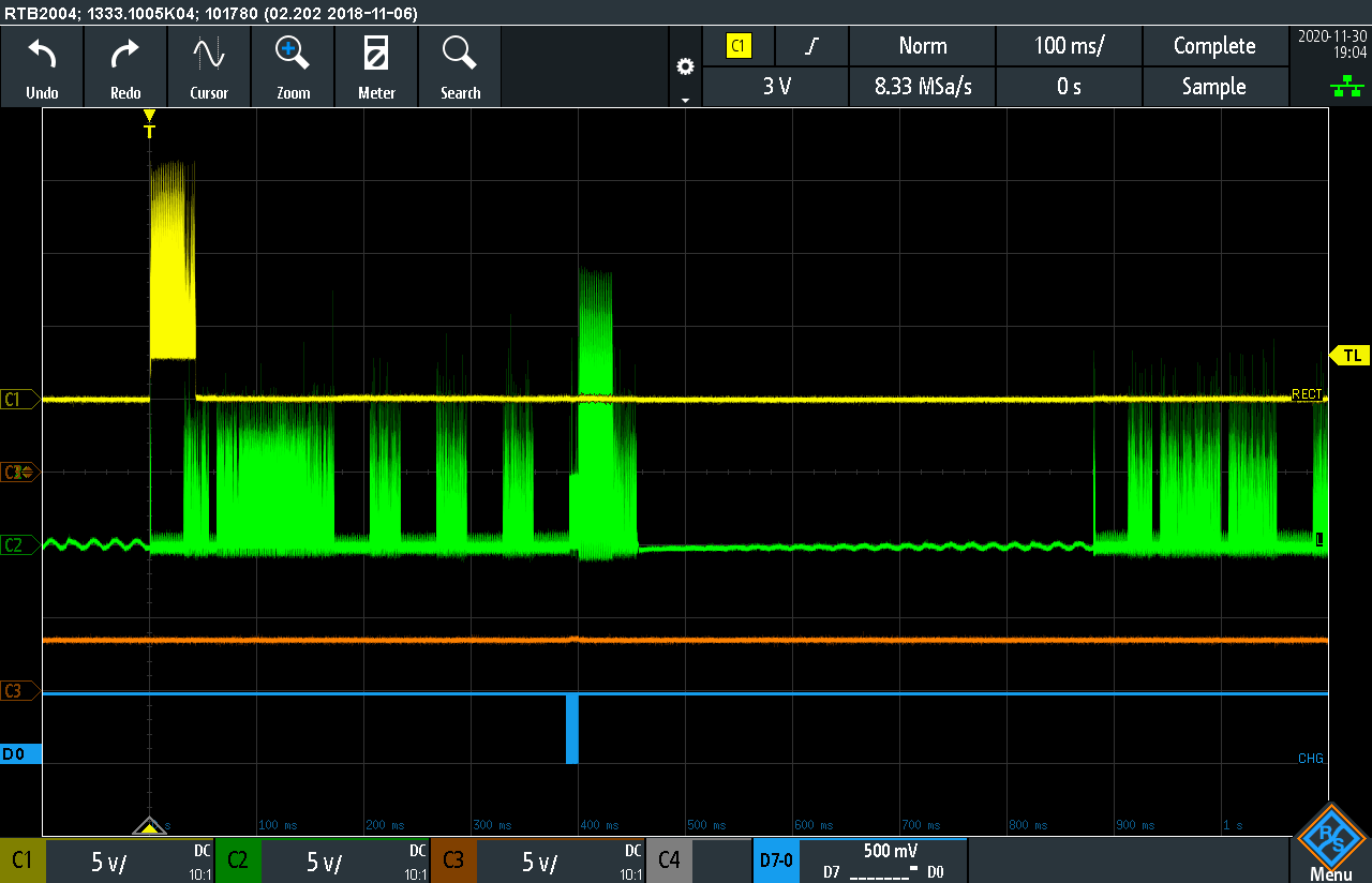
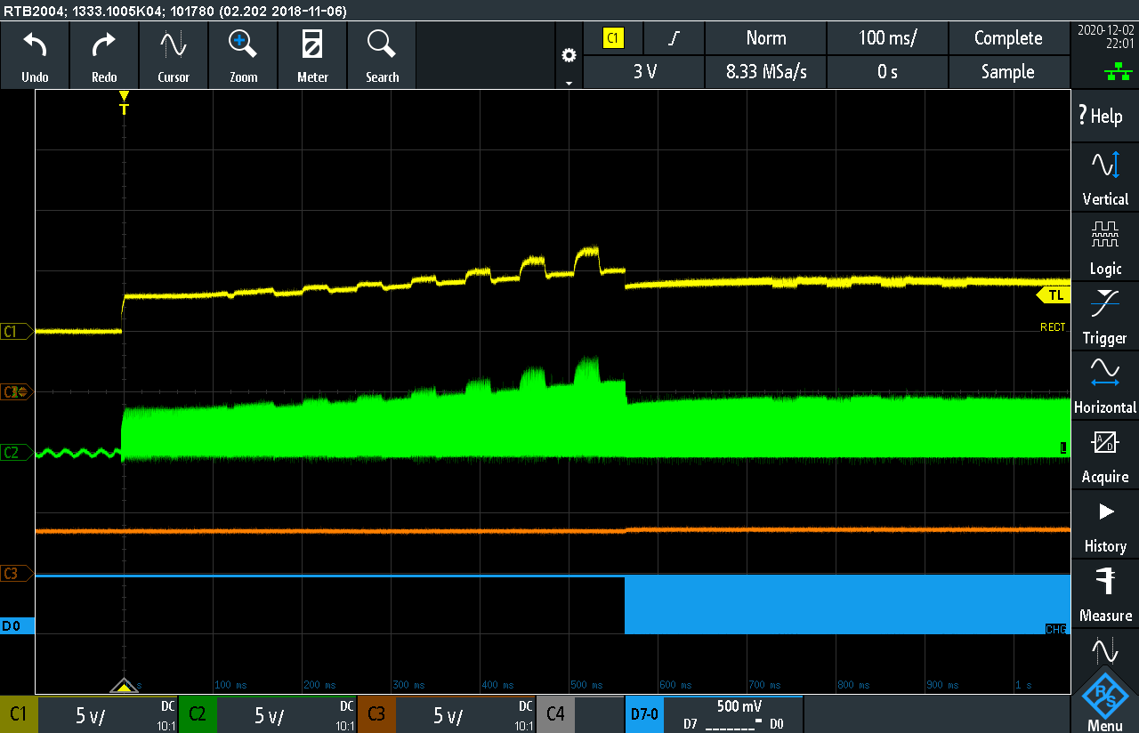
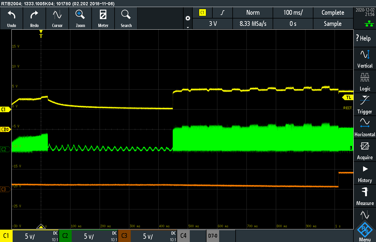
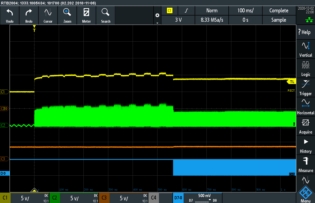
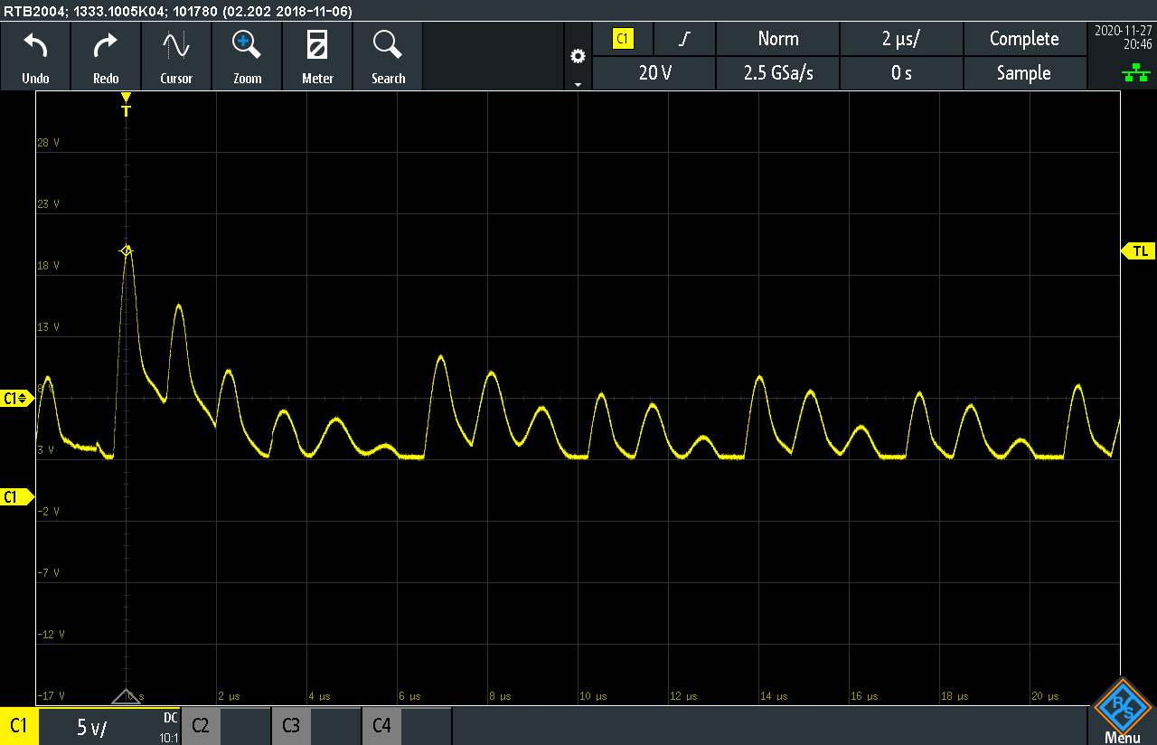
I read the FAQs and: my problem definitely isn't from overheating: I'm using either a 100mA or 500mA max charge current and the device does not get hot. I also looked at the voltage on the RECT pin. It does seem to get higher than the 7V threshold (sometimes much higher). I've enclosed some captures of the RECT pin, in various timescales. I'm not sure what the RECT pin is supposed to look like.

The problem here is that this is a hobby project, and resources are limited. No chance of using a sniffer, for example. I also have no way to measure Ls' in the prescribed manner. I have a scope, a bunch of assembled boards, some Wuerth coils, and I can make "educated guesses" :-)

What are the next steps, given my constraints?

  • Hello

    The RECT pin is a good test point, see attached.  Also include the OUT signal, it will turn on after the RECT reaches 7V.  Time base needs to be about 100ms.

    TX Start up and Comm Packets Guide.pdf

  • Hmm. Not sure what OUT is — I seem to have BAT and CHG in the bq51050B.

    My traces do not look anything like yours :-/

    C1 is RECT, C2 is AC2, C3 is BAT, and the blue D0 line is CHG.

  • Hello

    The RECT should be a DC signal, could have a small amount of AC ripple.  It is the full wave rectified AC1/AC2 signal that is filtered by the capacitors on RECT.

    Could you have a ground problem with the test set up or board?

    My mistake on OUT (BQ51013B) we want BAT (BQ51050B), the name changes between the two.

  • As I read "filtered by the capacitors on RECT", I thought to myself "what capacitors on RECT?". Well, as it turns out, the designer (that would be me) forgot to include the RECT capacitors in the design. A silly error, which was not caught by the design review team (er, that would be me) before prototypes were built. I have no idea how that happened.

    So. I rigged a horrible contraption by quickly soldering a THT 10uF cap on top of two 0402 components, the only place where RECT is accessible on the board, and indeed one could say the situation has been vastly improved :-)

    Please let me know how these traces look like. I'll keep thinking about how to rework those prototype boards, but it's likely it won't be possible, so I will need another spin. I'd like to know what else to look at before I do that.

    The first two screenshots are without the battery connected, so the C3 orange trace shows the voltage on the BAT pin with no battery. The last two also show the CHG output (D0, blue) — should it be oscillating like that?

  • Hello

    looks much better

    I would like to contact you using the private conversation feature.  Look for an email from system.

  • Working the problem off line.

    Will close this post, can re-open later if needed.