This thread has been locked.

If you have a related question, please click the "Ask a related question" button in the top right corner. The newly created question will be automatically linked to this question.

LM5088: start up problem - no load condition

Part Number: LM5088
Other Parts Discussed in Thread: LM5145, CSD18563Q5A

Hi,

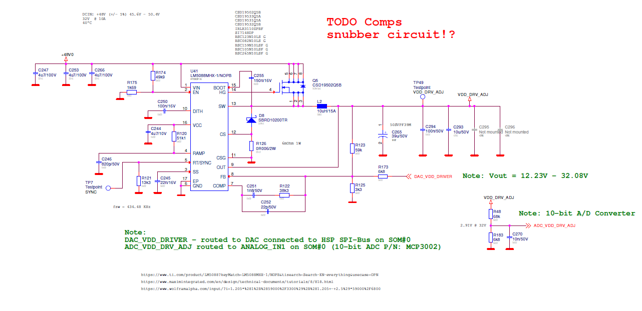
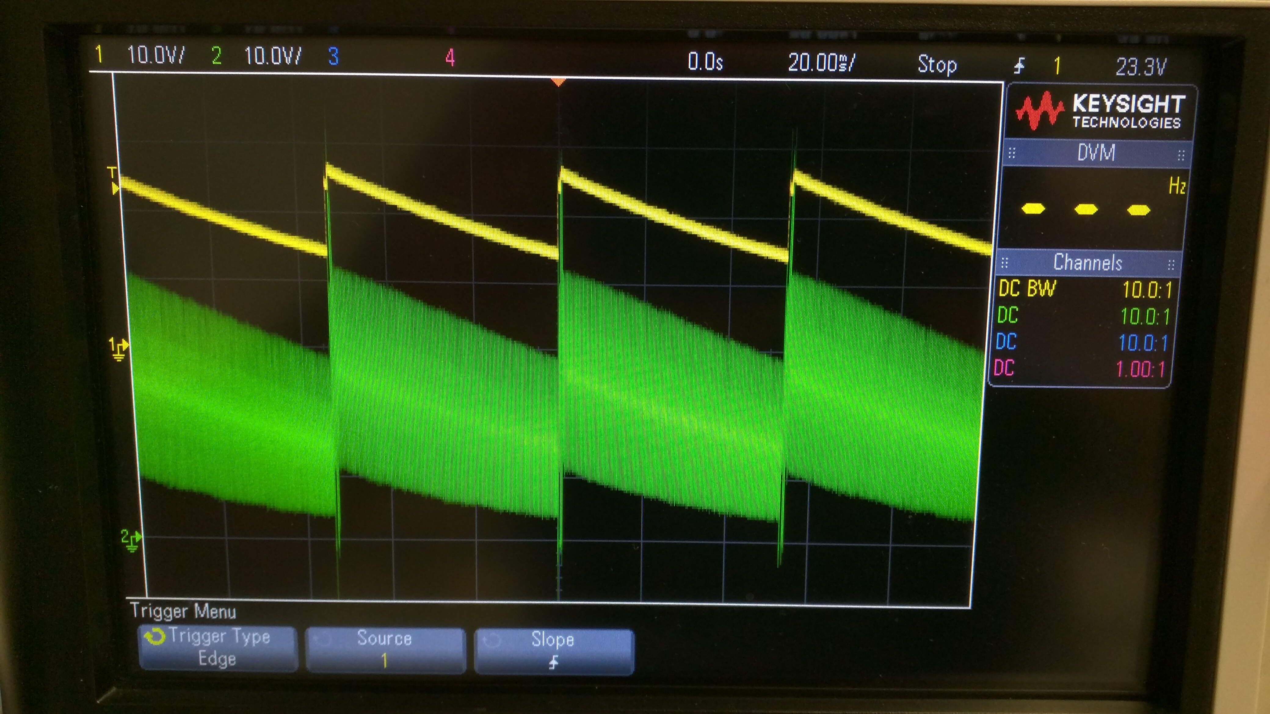
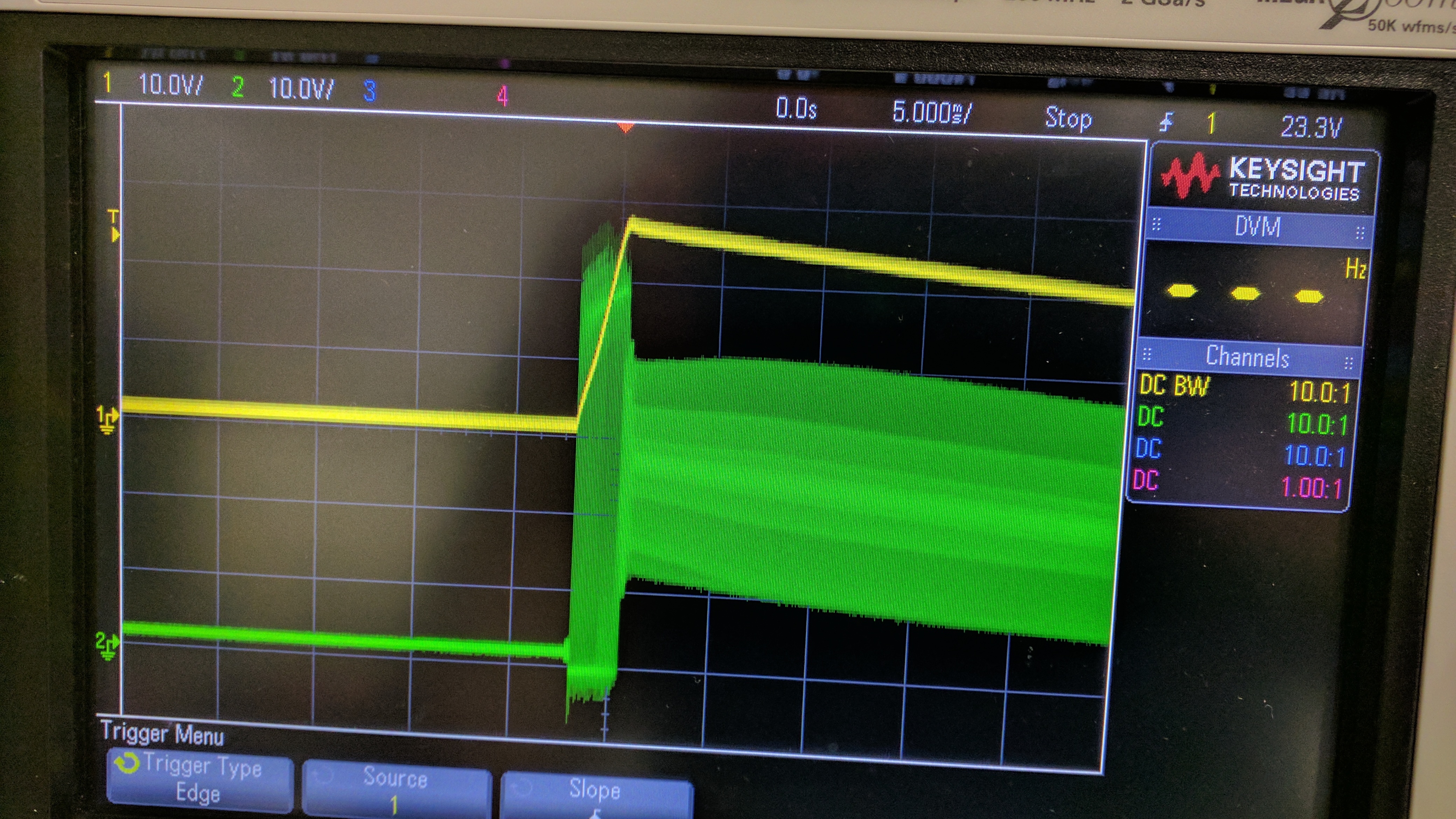
we wanna use a LM5088 to generate output voltages within a range of 12V to 32V. The Input Voltage is 48V. To control the output voltage we use a DAC which is connected to the output voltage divider through a series resistor, the DAC outputs voltages from 0V to 2.5V. On the prototyping boards the DAC is currently left unconnected. At no load we see that the output voltage is unstable and it seems the LM5088 is periodically enabled/disabled. At light load conditions it's maybe slightly better but we see some ringing at the output during the start-up. The Inductor is from Würth P/N:74435561100

www.we-online.de/.../74435561100.pdf

attached please find the schematic and some scope screenshots.

CH1 (yellow):  VOUT - VDD_DRV_ADJ

CH2 (green): LM5088-1 PIN#14 HG

Currently the Softstart is approx. 2.4ms. we have tried slower startup times but didn't had any luck

Thanks alot, David

  • Hi David,

    This looks like current limit is engaging at startup (you can measure the inductor current to confirm). Try increasing the SS cap from 22nF to 100nF based on the high Cout and the 6mOhm shunt.

    Given the 10A rated load current, you may want to use the LM5145 synchronous buck controller with high-side and low-side FETs. This reduces the power loss associated with the freewheeling diode D8 in your LM5088 design. DEMB can be tied high for CCM (aka FPWM operation at constant switching frequency) if that's preferable in the application. Please use the quickstart calculator available by download from the LM5145 product folder to assist with your design. An equivalent Excel calculator is available in the LM5088 product folder.

    Regards,

    Tim

  • By the way, the CSD19502 80V FET is quite capacitive. What is the switching frequency here...or is it based on the 13.3K RT resistor?

    Note that the VCC current related to the gate drive is Qg*Fsw where Qg is the gate charge of the FET at VGS = 7.8V. Make sure this current plus the controller quiescent current (3.8mA typ, 5.5mA max) does not exceed the VCC current limit min spec of 30mA. You can monitor the VCC voltage to check this.

    Regards,

    Tim

  • Hi Tim,

    thanks for your support. What does DEMB mean? I already increases the Soft-start up to 220n (approx. 24.1ms) that did not help. The switching frequency is based on the 13k3 Resistor which is around 434kHz, may quit high but I wanted to keep the Inductor small.

    I checked the PIN#16 with the scope. I see peridical voltage drops (1V) in a rate of 55ms. Does a series Resistor between the HG and Gate pin may help here? Or can you suggest us a proper alternative FET with the same footprint?

    Thanks alot and best regards,

    David

  • David,

    A good general purpose 60V NexFET in 5 x 6mm package is the CSD18563Q5A. You can add a series gate resistor (or a resistor in series with the boot cap to reduce the turn-on speed specifically), although I doubt switching noise is the issue here.

    Please measure [HG minus SW] differential voltage (i.e. the high-side gate drive), the VCC voltage, and the inductor current. Also, check your design with the LM5088 quickstart file, as mentioned.

    DEMB is the pin name to select diode emulation mode in our synchronous buck controllers (not applicable here as the LM5088 is a non-sync controller). A more applicable term is DCM (discontinuous conduction mode).

    Regards,

    Tim